
On this page
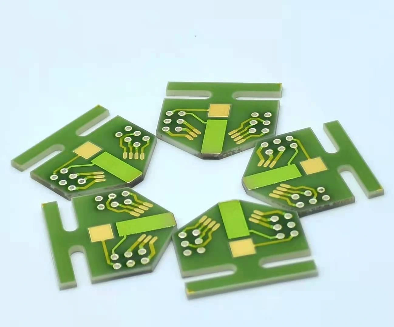
The safest pickup location on a miniature ceramic module may not be its geometric center or the electrical feature that must align during placement. When the part rotates on the nozzle, that offset rotates with it. A programme that translates the nozzle directly to the target pad coordinate can therefore place an apparently well-centered part incorrectly. Define the pickup, observed reference and electrical target as separate points and verify their relationship at more than one orientation.
System boundary
A rigid ceramic module transferred by a compatible pickup tool and placed relative to an electrical mating feature. The model concerns in-plane coordinates; pickup-force limits, machine calibration and final joining remain separate reviews.
Integration interfaces
| Interface | Required input | Thick film role | Validation owner |
|---|---|---|---|
| Nozzle to permitted pickup face | Contact footprint, rotation center and part-relative pickup position. | Provide the actual accessible surface without contact on vulnerable functional films. | Placement and ceramic owners approve the contact region. |
| Vision feature to electrical target | Asymmetric feature identity and measured target offset. | Preserve the specified pad relationship to the recognized feature. | Drawing and vision owners define the product coordinates. |
| Machine frame to receiving assembly | Target location, orientation and receiving fixture datums. | Align the intended electrical interface after transfer. | Assembly integrator verifies placed alignment. |
Integration risks
| Risk | Control or verification | Validation owner |
|---|---|---|
| The pickup offset is applied without rotating it. | Check an asymmetric witness at multiple commanded angles. | Placement programmer. |
| Vision locks to a similar but incorrect feature. | Use unique orientation evidence and reject ambiguous recognition. | Vision owner. |
| A machine coordinate pass conceals pad misalignment. | Inspect the functional placed feature in the receiving datum frame. | Assembly quality owner. |
System integration decisions
- Choose an allowed pickup region without redefining the product's functional datum.
- Rotate the pickup-to-target offset before calculating the commanded nozzle position.
- Measure final electrical alignment independently of whether the nozzle reached its programmed coordinate.
Name the pickup point, vision feature and target pad
Identify N, the actual rotation center associated with the pickup; V, the feature observed by the vision system; and P, the electrical feature whose position matters after placement. They may coincide, but that must be demonstrated rather than assumed. A broad empty region can be suitable for pickup while a remote pad defines the functional alignment.
Record each point in the product coordinate system and state the viewed face. Keep the receiving assembly's datum separate. This makes it possible to change an allowed pickup location without silently moving the electrical requirement. The nozzle must adapt to the approved product geometry; the geometry should not be redefined simply to make a programme's default center convenient.
Choose the pickup footprint from the real surface
Review the full contact footprint, not just its center. It must avoid wire loops, component bodies, fragile film boundaries and any surface reserved for bonding or soldering unless that contact has been specifically evaluated. A nozzle that fits a top-view empty space may still touch a raised feature because of part tilt or height variation.
Use the real ceramic outline, holes and populated features. Do not invent a flat pickup region on a product photograph or assume the reverse face is feature-free. The existing handling procedure governs suction, release and transfer damage. This placement calculation begins only after an appropriate contact region and tool have been selected.
Rotate the part-relative offset before translating the nozzle
Let the vector from nozzle point N to target feature P be d in product coordinates. At placement angle theta, rotate d into the receiving frame. The nozzle command is the desired target position minus that rotated vector. Applying the unrotated offset works only at the orientation for which that offset was originally expressed.
For an illustrative Cartesian example, d is (2.0, 1.0) mm and the desired target is (100.0, 50.0) mm. At zero degrees the nozzle position is (98.0, 49.0) mm. At positive ninety degrees counterclockwise, the rotated offset is (−1.0, 2.0) mm, so the nozzle must be at (101.0, 48.0) mm. Keeping the zero-degree command would miss the target by (−3.0, 1.0) mm.
p_N = p_target − R(θ)d; R(θ) = [[cosθ, −sinθ], [sinθ, cosθ]]
- p_N and p_target: nozzle and required electrical-feature coordinates in the receiving Cartesian frame, in mm.
- d: product-coordinate vector from nozzle rotation center to the electrical feature, in mm.
- θ: rotation from product frame to receiving frame, positive counterclockwise; use consistent angular units.
- R: dimensionless two-dimensional rigid rotation matrix.
Rigid planar part and calibrated common physical units. Camera pixel axes, mirrored views, machine angle conventions, tilt and nozzle runout need their own explicit transforms.
Separate nozzle calibration from product geometry
A nozzle can have runout or a camera-to-motion calibration error even when the product's pad-to-feature relationship is correct. Conversely, a perfectly calibrated machine cannot remove real variation between the vision feature and the required pad. Keep those contributors in separate records so a product measurement is not absorbed into a machine offset without explanation.
Rotate a suitable controlled witness through several orientations and observe the resulting feature positions using the approved calibration method. An orientation-dependent circle or repeated directional error suggests a different cause from a constant receiving-fixture translation. The witness must represent the relevant measurement geometry; a convenient image displayed on a monitor does not verify a physical nozzle rotation center.
Check angular uncertainty at the distant electrical feature
A small orientation error produces a larger positional effect at a feature farther from the rotation reference. For a first-order screen, transverse displacement is approximately distance times angular error in radians. A target 6 mm from the reference with an assumed 0.2-degree angular error has about 0.0209 mm transverse displacement.
That illustrative value is not a placement capability. Add it to the relevant functional budget without counting the same vision uncertainty twice. A nearby outline edge may appear well aligned while a distant narrow pad loses overlap. Select inspection features that challenge the electrical interface, not only a central feature insensitive to rotation.
Make orientation recognition unambiguous
Repeated pads, symmetric outlines and glossy glass can give several plausible vision matches. Define an asymmetric feature or combination of features that distinguishes the intended orientation. Preserve reference images and rejection conditions so an ambiguous match is not automatically accepted because its score exceeds a generic threshold.
Test the recognition on actual permitted surface variation without digitally changing product geometry. If the pickup tool obscures the orientation feature, choose another observable relationship or inspect before pickup with a traceable transfer. Manual fallback requires its own controlled method. Guessing a rotation after the primary reference disappears undermines the coordinate model even if the final part looks centered.
| Pattern | Focused check | Potential correction |
|---|---|---|
| Correct at zero degrees, wrong after rotation | Verify rotated pickup-to-pad vector | Correct transform order or offset convention |
| Same translation at every orientation | Check receiving fixture and frame origin | Correct the relevant common offset |
| Position follows a circular pattern with angle | Check nozzle rotation-center calibration | Recalibrate the physical tool relationship |
| Central feature passes but distant pad misses | Check angle and target distance | Improve orientation observation or budget |
| Occasional reversed parts | Inspect unique-feature recognition | Reject ambiguous orientation states |
Measure alignment after the part leaves the nozzle
A commanded position is not the final placed position. Release, seating, attachment material and subsequent fixture contact can move the part. Observe the electrical target after the intended placement state is complete, using the receiving assembly's functional datums. Keep before-release and after-release results separate when diagnosing a shift.
If the target moves only after release, changing the pickup-coordinate offset may compensate one condition while hiding unstable seating. Investigate the physical placement interface first. Check whether the nozzle drags the part during withdrawal or whether uneven attachment material creates rotation. The relevant correction must remain reproducible across the approved part and receiving-surface ranges.
Hand off a coordinate contract rather than one programmed number
Provide the permitted contact footprint, N/V/P point definitions, viewed face, angle convention, product offsets and receiving targets. Include the transform example used to verify sign and rotation order, plus the calibration identity and final feature measurements. A small coordinate table is more useful than a screenshot without origins or units.
Reopen the review after changing nozzle geometry, pickup location, vision feature, product artwork, receiving fixture or placement orientation. Keep the physical drawing master unchanged unless the design owner approves a genuine product revision. This preserves the distinction between a machine programme adjustment and a change to the customer's electrical alignment requirement.
Send the pickup and electrical placement coordinates
Provide the physical pickup region and functional target separately so an asymmetric ceramic module can be placed with a verified transform.
- Actual product views and allowed pickup footprint with nearby height and no-touch features.
- Nozzle center, recognized vision feature and target-pad coordinates in stated units and viewed face.
- Receiving datum, required orientation, functional overlap allowance and relevant angular uncertainty.
- Machine calibration identity and before/after-release measurements at several orientations.
The drawing-upload form loads as you reach this section.