
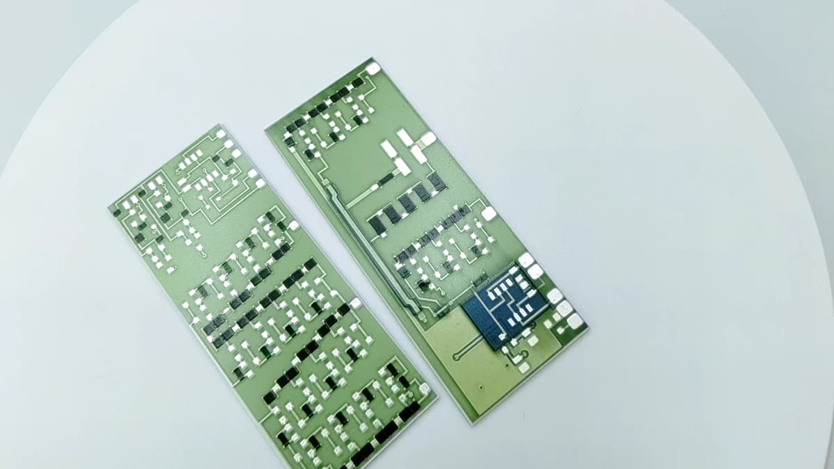
Overview
High-temperature suitability belongs to the complete construction and its service boundary, not to one paste name or a furnace peak. This is a qualification framework, not a catalog of approved ChipSimple material stacks or operating ranges. this guide separates operating exposure from manufacturing firing, then reviews substrate, conductor, resistor, dielectric or overglaze, terminals, joining, refire history, atmosphere, and validation as a coupled material system.
Engineering review matrix
Each row links a design variable to evidence that can support a drawing or release decision.
| Variable | Control question | Verification route |
|---|---|---|
| Service temperature profile | Separate local circuit temperature, ambient, gradients, ramp rate, dwell, cycles, transients, and faults at the intended measurement location. | Use an agreed instrumentation and exposure method on a representative assembly or bounded test article. |
| Manufacturing firing profile | Record the paste-specific atmosphere, peak, dwell, belt or batch context, and refire history only as manufacturing conditions. | Compare the actual process record with the released material sequence; never publish it as a service-temperature capability. |
| Substrate system | Review composition, surface condition, thickness, flatness, thermal expansion, thermal transport, and compatibility using the specified grade and source. | Confirm the actual substrate record and construction-specific evidence rather than relying on a generic ceramic label. |
| Functional film stack | Treat conductor, resistor, dielectric, overglaze, and any intermediate layer as one named and revision-controlled compatibility set. | Review current material data and processed samples after the full firing or cure sequence. |
| Termination and joining | Include pad finish, wire bond, braze, solder, weld, adhesive, connector, and strain-relief interfaces that may see the exposure. | Test the selected joining route and inspect the interface after the representative thermal history. |
| Atmosphere and media | Identify air, inert or controlled atmosphere, vacuum, humidity, condensation, fuel, oil, cleaning chemistry, sulfur-bearing media, and pressure as applicable. | Condition and expose samples to the stated media; do not transfer an air result to another environment. |
| Electrical and mechanical load | Combine voltage, current, power density, pulse, self-heating, mounting restraint, vibration, and thermal-expansion mismatch with the service profile. | Measure the required electrical function and inspect mechanical interfaces under the agreed combined conditions. |
| Change control | Define which material source, formulation revision, layer sequence, firing route, geometry, joining, or protection changes reopen qualification. | Link the disposition and revalidation decision to the affected drawing, lot, and evidence records. |
Material-system qualification method
The order makes assumptions and ownership visible before a result is promoted to a requirement.
- 01
Define the service exposure
Record steady, cyclic, transient, and fault temperatures at the circuit and interfaces together with time, atmosphere, humidity, pressure, media, bias, load, and storage. Do not substitute a heater setpoint or furnace peak for this envelope.
- 02
Name every layer and interface
Identify substrate, conductor, resistor, dielectric, protective layer, terminal, attachment, component, housing, and any dissimilar material. Mark each item as specified, proposed, unknown, or outside the supply scope.
- 03
Review processing compatibility
Check printing or deposition route, drying, atmosphere, firing profile, refire count, sequence, cleaning, joining, and later thermal operations against the named materials. Firing conditions describe processing, not field endurance.
- 04
Build representative validation
Choose coupons or prototypes that preserve the critical film geometry, interfaces, termination, protection, mounting, and load. Measure agreed functions before, during when needed, and after representative exposure.
- 05
Release only a qualified boundary
If construction-specific validation supports the decision, tie approved material revisions, process route, application limits, inspection methods, results, exceptions, and change-control triggers to the drawing revision. Leave unsupported ranges out of the public page.
- 06
Separate reversible change from permanent damage
Define stabilized pre-exposure, hot, cooled, and recovery measurement states for resistance, insulation, adhesion, continuity, geometry, and other project functions. A temporary temperature-dependent shift, measurement drift, connector change, permanent film change, crack, delamination, oxidation, or joint degradation can produce similar endpoint data but require different decisions. Record sensor location, dwell, electrical bias, atmosphere, fixture, measurement timing, uncertainty, and visual evidence so the reviewer can distinguish an operating response from irreversible construction damage.
- 07
Assign the qualification owners
Place material compatibility, printed processing, joining, housing, atmosphere, electrical loading, safety, final-system exposure, and acceptance under named project owners. State which evidence is supplier literature, company process evidence, prototype characterization, qualified-laboratory work, or OEM system validation. The release record must also identify who approves deviations and which changes reopen testing. This prevents a component coupon from being treated as approval of an enclosure, terminal, control system, fluid boundary, regulatory requirement, or complete application that the coupon never represented.
Failure controls
These are review prompts, not evidence that every risk applies or that every test is available.
- A
A firing-process temperature being rewritten as a product operating-temperature rating
- B
One high-temperature ingredient being used to imply that the complete stack and assembly are qualified
- C
Thermal-expansion mismatch causing cracking, delamination, or termination stress during cycling
- D
Refire or downstream joining changing an earlier film or interface outside its reviewed state
- E
Oxidation, reduction, contamination, migration, corrosion, or media attack altering electrical function
- F
Self-heating and local hot spots making the measured circuit temperature differ from ambient or setpoint
- G
A laboratory coupon omitting the geometry, mounting, protection, or interface that governs the real failure mode
Reference boundary
Public method sources
These sources support the engineering method and terminology used in this technical guide. They do not establish a ThickFilmPCB material list, capability limit, customer result, certification, or finished-product specification.
- 01Heraeus R900R high-temperature resistor system
Supports the method boundary that a service-temperature statement belongs to a named resistor, conductor, overglaze, substrate, and processing system and remains distinct from firing conditions; listed values are Heraeus-specific and not ChipSimple capabilities.
- 02Heraeus thick-film technology for heater applications
Supports reviewing substrate, dielectric, conductor, resistor, protective overglaze, and their different process sequences as a complete route; all product examples and typical processing values remain supplier-specific.
- 03IEC 60068-2-14:2023 — Change of temperature
Supports specimen-specific temperature-change conditions, severities, tolerances, and test reporting only; it does not define a product operating-temperature rating or prove ChipSimple environmental-test scope.
Inputs for a practical review
Unknown values may be labelled unknown. The review should convert uncertainty into an explicit decision or validation task.
Send Drawings- 01
Service temperature profile at the circuit, including dwell, ramps, cycles, transients, and faults
- 02
Atmosphere, pressure, humidity, condensation, chemicals, fuels, oils, cleaning, and storage exposure
- 03
Substrate identity and the complete conductor, resistor, dielectric, protection, and termination stack
- 04
Printing or deposition, drying, firing or cure, refire, cleaning, and joining sequence
- 05
Voltage, current, power, pulse, duty, self-heating, and permitted functional change
- 06
Mounting, housing, component, bond, solder, braze, adhesive, connector, and strain interfaces
- 07
Required visual, electrical, adhesion, environmental, aging, and post-exposure checks
- 08
Prototype configuration, sample plan, acceptance criteria, records, and change-control expectations