
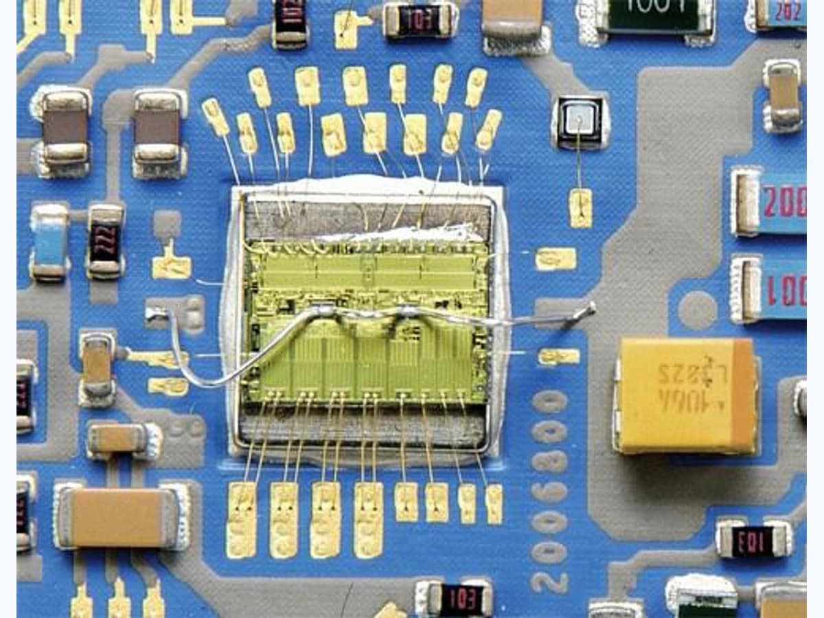
Overview
Wire-bondable metallization is a complete pad-and-bond system, not a generic gold-colored or silver-colored surface. Substrate, fired conductor, optional top metallization or finish, pad geometry, surface roughness and contamination, firing and storage history, wire material and diameter, ball or wedge process, ultrasonic and force settings, temperature, loop geometry, encapsulation, handling, and environment all influence bond formation and durability. Material-selection guidance cannot claim bond quality; executable pull, shear, visual, destructive physical analysis, and environmental evidence belong to defined methods and the exact assembly configuration.
Engineering review matrix
Each row links a design variable to evidence that can support a drawing or release decision.
| Variable | Control question | Verification route |
|---|---|---|
| Metallization stack | Name every fired and deposited layer, thickness observation, substrate, firing/refire, finish, diffusion barrier, supplier/revision and substitutions. | Use material genealogy plus surface, section or other justified evidence on representative pads. |
| Wire and bond method | Define wire material/diameter, ball/wedge/ribbon, first/second bond, tool, force, ultrasonic, time, temperature and machine program. | Retain actual setup and process records with bond maps and results. |
| Pad geometry and surface | Set pad dimensions, pitch, conductor entry, edges, flatness, roughness/cleanliness criteria, probing, access and storage exposure. | Inspect drawing-linked pads before bonding and correlate locations with failure modes. |
| Electrical and thermal load | Define current waveform, voltage, parallel sharing, pulse, ambient, die/substrate temperature, neighboring heat and fault cases. | Measure relevant electrical/thermal response on the finished assembly, not wire resistance alone. |
| Package and downstream process | Specify die attach, cleaning, encapsulant, cure, lid, atmosphere, handling, loop clearance, vibration and rework. | Inspect loops and bonds and repeat selected tests after complete packaging stages. |
| Test and failure mode | Define pull/shear method, specimen, fixture, direction, rate, sample, destructive/non-destructive sequence, acceptance and failure categories. | Use controlled equipment and retain raw force, location, image and failure-mode records. |
| Environment and change | Set storage, humidity, temperature cycling, corrosion, vibration, load, aging, cleaning, material/tool/process changes and traceability. | Test configuration-linked samples and reopen qualification after affected changes. |
Controlled model
Pad-system and bond-process comparison
Selection must use the exact wire and bonding mechanism. Electrical resistance alone cannot establish intermetallic behavior, ultrasonic coupling, pad adhesion, contamination tolerance, cratering, heel fatigue, corrosion, or encapsulation compatibility.
J_avg = I/A_wireAverage current-density screen in a bond wire.
- Units
- A/m²
- Use boundary
- Does not predict fusing, heel heating, parallel-wire sharing, pulse behavior, loop cooling, bond-interface temperature, or reliability.
R_wire = ρL/A_wireFirst-order wire electrical resistance.
- Units
- Ω
- Use boundary
- Use actual wire material, length, area and temperature; bond contact, loops, neck geometry and process variation require measurement.
Decision comparison
| Decision | Route A | Route B | Verification |
|---|---|---|---|
| Direct bondable fired conductor versus added finish | A direct route reduces interfaces but must provide a compatible, stable fired surface and pad adhesion for the named wire/process. | An added finish can tailor the surface but introduces deposition, thickness, porosity, adhesion, diffusion, contamination, masking, storage and supplier controls. | Bond and test both production-intent routes after complete processing and relevant storage/environment, recording failure location and pad condition. |
| Gold-wire versus aluminum-wire system | Gold-wire bonding brings one set of pad-chemistry, temperature, ultrasonic, intermetallic and corrosion considerations. | Aluminum-wire bonding brings another set of oxide, ultrasonic, pad compatibility, loop and corrosion considerations. | Use the project's named material pair and bonding method; never infer interchangeability from a pad label. |
- Pad lift, interface separation, wire break, heel break, cratering and cohesive wire failure do not carry the same diagnosis; record failure mode rather than reporting force alone. Surface contamination can arise from firing, handling, storage, cleaning, probing, adhesives or enclosure processes, so cleanliness control spans the entire route.
- A supplier data sheet can support material screening, but only company-controlled builds and reviewed test records could support a ChipSimple capability statement. The quality page owns the executable pull/shear method, specimen, loading, sample count, acceptance and equipment evidence.
Failure controls
These are review prompts, not evidence that every risk applies or that every test is available.
- A
Selecting a pad by color or generic metal name without the exact fired stack, finish, wire and bonding process.
- B
Using bond force alone while ignoring failure location, pad lift, cratering, heel damage, surface contamination and loop condition.
- C
Probing, handling, storage, cleaning, adhesives or enclosure work contaminating a qualified surface before bonding.
- D
Changing wire, tool, ultrasonic program, pad lot, finish supplier, firing/refire, cleaning or encapsulant without requalification.
- E
Assuming electrical continuity proves mechanical integrity or long-term environmental reliability.
- F
Treating the macro photograph as proof of material, bond quality, strength, process, equipment or capability.
Wire-bond metallization workflow
The order makes assumptions and ownership visible before a result is promoted to a requirement.
- 01
Define the bond system
State wire material, diameter, ball/wedge/ribbon route, bond sequence, current and pulse, loop, die and package geometry, pad pitch, substrate, operating environment, encapsulation, lifecycle and acceptance ownership.
- 02
Map candidate stacks
Name fired conductor, top metallization or finish, substrate, print/fire/refire, thickness and surface requirements, storage, cleaning, masking, compatible wire, downstream materials and substitutions.
- 03
Design pads and access
Dimension pad area, pitch, edge clearance, conductor entry, adjacent potentials, flatness, surface, probe restrictions, bond direction, tool access, loop clearance, die attach, enclosure and rework boundaries.
- 04
Control surface and process
Define material identity, firing, finish deposition, handling, storage time and atmosphere, cleaning, inspection, bonder setup, force, ultrasonic energy, time, temperature, tool, wire lot and traceability without inventing settings.
- 05
Evaluate bond evidence
Inspect pads and bonds, execute project-selected pull/shear or other methods, record actual settings and failure locations, and correlate with surface, pad adhesion, electrical path and destructive analysis where justified.
- 06
Validate lifecycle and changes
Repeat relevant tests after storage, assembly, encapsulation, thermal cycling, humidity, vibration, electrical load and aging. Lock wire, pad, finish, process, tooling, cleaning, package and requalification triggers.
Reference boundary
Public method sources
These sources support the engineering method and terminology used in this technical guide. They do not establish a ThickFilmPCB material list, capability limit, customer result, certification, or finished-product specification.
- 01NASA NTRS — Update to the Body of Knowledge for Copper Wire Bonds
Supports configuration-specific wire, pad, process-window, corrosion, failure-mechanism, test, and qualification considerations. It does not approve a ChipSimple metallization, wire, bond process, or reliability result.
- 02MIL-STD-883 — Microcircuits test methods
Supports defined microcircuit bond-strength and inspection test-method context where contractually applicable. It provides no automatic acceptance or company capability.
- 03Heraeus C2130B conductor data sheet
Supports one named fired conductor's processing and stated assembly-test context only; values are not transferable to another wire-bond stack.
Inputs for a practical review
Unknown values may be labelled unknown. The review should convert uncertainty into an explicit decision or validation task.
Send Drawings- 01
Wire material/diameter, bond type, current/voltage waveform, loop geometry, die and package drawing, pad map and clearances.
- 02
Substrate, fired conductor, finish, layer thickness requirements, firing/refires, storage, handling, cleaning and substitutions.
- 03
Pad size/pitch, conductor entry, edges, flatness/surface, probing, tool access, loop/enclosure clearance and tolerances.
- 04
Bonder/process requirements, tool, force/ultrasonic/time/temperature controls, wire lot, traceability and rework.
- 05
Die attach, encapsulation, cure, lid, atmosphere, thermal, humidity, vibration, load, storage and lifecycle exposures.
- 06
Visual, pull, shear, electrical, destructive analysis, sampling, failure modes, acceptance, reports and qualification ownership.
- 07
Prototype quantities, variants, drawing revision, material/process genealogy, change triggers and named reviewers.