
Overview
A moving contact path is an interface among a printed resistive or conductive surface, wiper material, force system, motion, current, environment, and readout circuit. It must deliver the required transfer while surviving repeated travel without intermittent output, destructive wear, debris buildup, corrosion, or shorting. Track width and outline cannot be selected independently from contact footprint, pressure distribution, travel direction, speed, landing zones, terminals, protection openings, housing, fluid or contaminant exposure, and mechanical tolerance. This page owns the general contact-path decision; application-specific fuel-level, rotary, and linear transfer laws remain with their respective owners.
Failure controls
These are review prompts, not evidence that every risk applies or that every test is available.
- A
Selecting force from a generic contact rule without the actual materials, footprint, surface, motion, current, fluid, and housing tolerance.
- B
Measuring only slow averaged output and missing short interruptions, chatter, debris events, or directional differences that matter to the controller.
- C
Allowing a wiper to cross protection edges, terminal steps, narrow necks, print defects, or substrate boundaries not represented in a coupon test.
- D
Changing fluid, additive, lubricant, cleaning, wiper finish, ink, cure or firing, force, speed, or readout filter while reusing old life evidence.
- E
Using system calibration to mask progressive wear, contact instability, corrosion, mechanical movement, or non-monotonic raw output.
- F
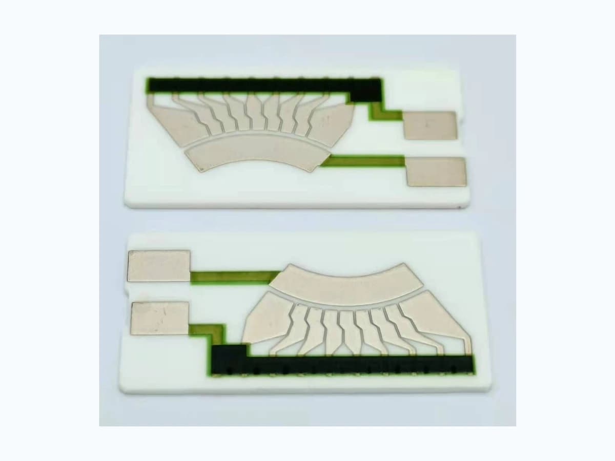
Claiming fuel, oil, wear-life, noise, or automotive performance from the photographed resistor card alone.
Controlled model
Contact pressure, electrical path, and wear-screen model
Use simple models to expose inputs, not to predict life from first principles. Real contact occurs through asperities and a changing footprint. Surface films, debris, lubricant or fluid, speed, vibration, current, temperature, and wear alter constriction and film resistance. Only representative moving-contact tests can validate a specific material pair and mechanism.
p_nom = F_n / A_appNominal contact pressure from normal force over an apparent footprint.
- Units
- Pa
- Use boundary
- Actual pressure is nonuniform and concentrated at asperities or contact fingers; geometry, compliance, roughness, tilt, motion, and wear require measurement or representative testing.
V_contact = I_s R_contactVoltage disturbance associated with contact resistance at signal current.
- Units
- V
- Use boundary
- R_contact can vary dynamically and includes constriction, surface films, debris, vibration, and measurement bandwidth. Do not infer it from bulk material resistivity.
D = |y_forward(x) − y_reverse(x)|Defines directional output difference at the same commanded position.
- Units
- Output units or normalized ratio
- Use boundary
- Includes mechanical backlash, wiper footprint, contact, track, timing, and measurement effects; the coordinate reference and sweep conditions must be fixed.
Decision comparison
| Decision | Route A | Route B | Verification |
|---|---|---|---|
| Single finger versus redundant fingers | One finger provides a localized path but is sensitive to local debris, surface defects, alignment, and force variation. | Multiple fingers may add contact redundancy and averaging but widen the effective footprint, redistribute force, generate debris, and complicate current sharing. | Measure footprint, force, dynamic contact behavior, transfer residual, and wear under the exact material, motion, environment, and readout conditions. |
| Exposed path versus selective protection | The active sliding zone must remain accessible to the wiper and may require a controlled surface state. | Adjacent protection can shield conductors and resistors but its edge, thickness, registration, chemistry, and wear interaction can disturb the contact transition. | Inspect fired or cured openings and edges, cycle the full path including transitions, and record deposits, scratches, intermittent events, and electrical drift. |
- Low-level measurement current may not reproduce switching or wetting behavior at another electrical state; the RFQ must define the real signal circuit.
- Fluid-level imagery does not prove compatibility with any named fuel, oil, additive, cleaning agent, or regulation.
Contact-path engineering workflow
The order makes assumptions and ownership visible before a result is promoted to a requirement.
- 01
Define motion and signal
Specify linear or rotary travel, direction, speed, acceleration, dwell, overtravel, landing, vibration, output law, excitation, current, load, filtering, sampling, interruption threshold, noise bandwidth, hysteresis, and calibration.
- 02
Define the contact pair
Name printed track and collector materials, conductor terminations, wiper material and finish, finger shape, footprint, force, compliance, edge condition, lubrication or fluid, surface preparation, protection, and cleaning. Do not substitute materials by appearance.
- 03
Build the tolerance map
Dimension card location, wiper path, radius or lateral position, tilt, runout, backlash, force stack, housing, stops, printed registration, fired width, protection openings, terminals, and substrate edges at nominal and worst credible combinations.
- 04
Control transitions and current
Review entry and exit zones, conductor-to-resistor transitions, collector, end stops, inactive bands, local widths, current density, self-heating, lead and connector resistance, electrochemical potential, and any switching events.
- 05
Test the complete mechanism
Measure mechanical reference, force, raw electrical output, contact interruptions, direction difference, temperature, speed, vibration, and medium state on production-intent assemblies. Use event capture fast enough for the defined functional risk.
- 06
Assess wear and freeze changes
Inspect track and wiper at controlled intervals for polish, grooves, film transfer, particles, corrosion, protection damage, and substrate wear. Correlate physical observations with output change and lock materials, processes, geometry, housing, and test rules.
Engineering review matrix
Each row links a design variable to evidence that can support a drawing or release decision.
| Variable | Control question | Verification route |
|---|---|---|
| Track and collector geometry | Define active path, width, thickness observation, transitions, terminals, collector, gaps, protection openings, edge distances, registration, and fired tolerances. | Inspect drawing-linked features and correlate geometry with position-output and event data. |
| Wiper material and footprint | Set alloy or material, finish, finger count, edge, radius, apparent contact area, orientation, cleanliness, and approved substitutions. | Inspect the production-intent contact and record footprint or witness pattern and post-cycle condition. |
| Force and compliance | Allocate spring force, tolerance, deflection, tilt, card flatness, housing stack, vibration, thermal expansion, and wear-related relaxation. | Measure force or justified proxy across position, assemblies, temperatures, and lifecycle stages. |
| Electrical interface | Define excitation, signal current, load, connector, grounding, leakage, filter, bandwidth, sampling, interruption, and fault thresholds. | Capture raw high-rate output and system-filtered output separately under real motion and electrical states. |
| Motion profile | Specify range, direction, speed, acceleration, dwell, reversals, overtravel, total travel distribution, vibration, and powered state. | Use controlled motion records and repeat key profiles at environmental and lifecycle checkpoints. |
| Environment and media | Name temperature, humidity, fluid formulation, additives, particles, condensation, cleaning, storage, pressure, and oxygen exposure where relevant. | Retain media identity and conditions and inspect electrical, chemical, and physical changes after defined exposure. |
| Acceptance and lifecycle | Define curve error, noise bandwidth, interruption, hysteresis, drift, resistance, visual wear, failure mode, sampling, intervals, traceability, and changes. | Use configuration-linked baseline and interval data with raw traces, event rules, inspection images, and uncertainty. |
Reference boundary
Public method sources
These sources support the engineering method and terminology used in this technical guide. They do not establish a ThickFilmPCB material list, capability limit, customer result, certification, or finished-product specification.
- 01SAE 2002-01-1074 — Design Guidelines for Automotive Fuel Level Sensors
Supports treating thick-film material, moving contact, wear, noise, failure modes, and fuel chemistry as coupled design inputs. It does not establish a ChipSimple contact system or life result.
- 02SAE 921450 — Reliable Measurement of Fuel Level
Supports system-level review of moving contact, resistor, mechanism, housing, and indication. Its application example is not a universal contact-path specification.
- 03NIST Technical Note 1297 — measurement uncertainty
Supports uncertainty treatment for force, position, electrical output, repeatability, timing, and model contributions; it supplies no wear or contact-performance limit.
Inputs for a practical review
Unknown values may be labelled unknown. The review should convert uncertainty into an explicit decision or validation task.
Send Drawings- 01
Target position-output law, travel, direction, speed, acceleration, dwell, overtravel, stops, resolution, monotonicity, hysteresis, and error budget.
- 02
Excitation, signal current, source/load, filtering, sample rate, bandwidth, interruption definition, connector, grounding, calibration, and diagnostics.
- 03
Track, collector, terminals, protection, printed materials, firing or cure, wiper material/finish, footprint, force, compliance, and cleaning.
- 04
Mechanism drawings with wiper path, card datums, housing, pivot or guides, runout, tilt, backlash, flatness, tolerance stack, and assembly sequence.
- 05
Temperature, humidity, media identity, additives, particles, vibration, shock, storage, powered state, and lifecycle motion profile.
- 06
Test fixture, mechanical reference, force method, output capture, wear inspection, event logic, intervals, uncertainty, and acceptance criteria.
- 07
Prototype variants, sample quantities, traceability, drawing and software revisions, substitutions, reports, and requalification triggers.