
On this page
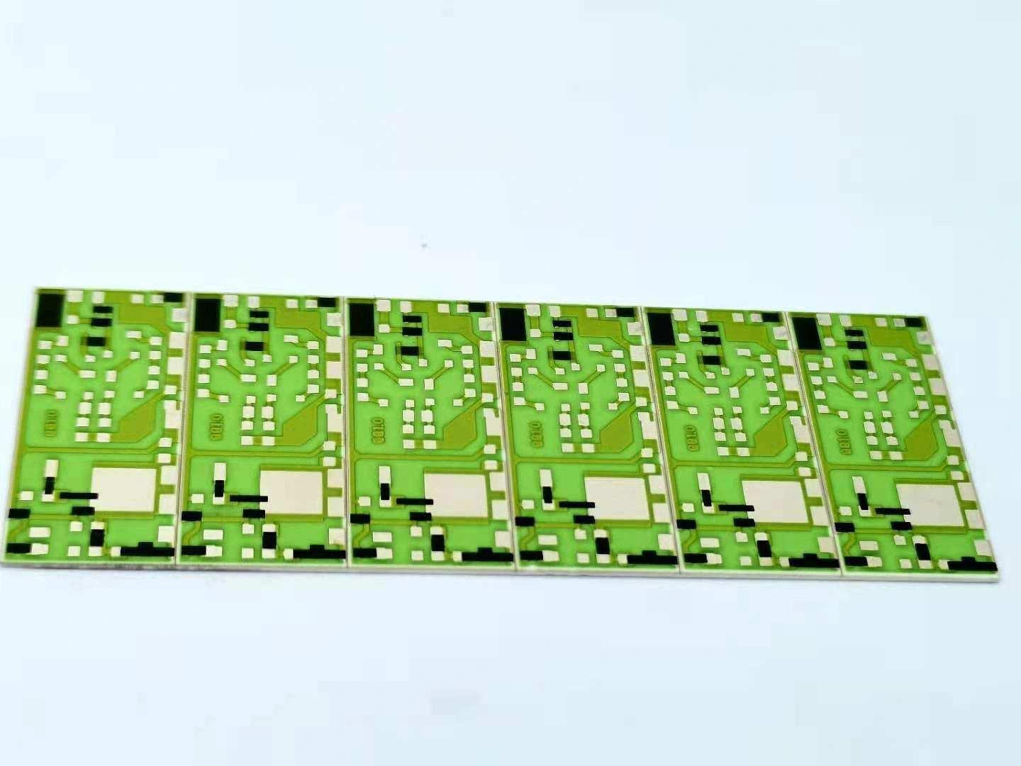
A ceramic edge termination may look continuous from the main face while a narrow uncoated region remains where a fixture contacted the edge during deposition or handling. A later singulation chip can create a similar exposed-ceramic signature. The two causes require different corrective actions. A useful process review maps the complete perimeter, fixture contact locations and inspection stage so a shadow formed during deposition is not blamed on cutting, and cutting damage is not hidden by changing the termination artwork.
Key design decisions
- Define functional edge zones and fixture contacts in one perimeter coordinate system.
- Inspect after deposition and after every edge-loading operation to locate when exposure first appears.
- Evaluate remaining conductive path and adhesion with drawing-specific methods rather than judging color continuity alone.
Define what the edge termination must connect
Start from the electrical and assembly function. Identify the face pad, edge band, opposite-face feature if present, and the regions needed for contacting, shielding, grounding or later joining. Mark ceramic corners, scribe or cut lines, coating boundaries and mechanical keep-outs. This is not a generic wraparound design exercise; the purpose is to identify where an as-built termination must remain present after the chosen support and separation sequence.
Divide the perimeter into addressable segments measured from stable datum features. Clockwise distance from a corner can work for a rectangular substrate, while a drawing-defined angular coordinate may suit a circular part. Photographing only the most visible face loses the relation between a gap and the fixture. Preserve face, edge and transition views with the same segment labels.
Record every fixture contact and hidden surface
Create a fixture-contact map before interpreting an exposed patch. Include supports, clamps, vacuum lands, carrier rails and any temporary masks. Record whether contact occurs during deposition, drying, firing or transport. A small support that is harmless for a face print can block access to an edge band or disturb a wet deposit during release.
Fixture drawings show intended contact, but witness marks and photographs reveal actual contact. Compare both. If contact shifts with substrate tolerance or loading, record the possible range rather than one ideal line. Do not claim that a visible fixture in a representative image is company equipment or that it establishes production capability; the diagnostic method remains applicable only after the actual fixture is documented.
Quantify the exposed fraction of a functional segment
For a defined perimeter segment, compare the measured exposed length with the total required conductive length. In a hypothetical example, 0.30 mm of exposed ceramic within a 4.0 mm functional edge segment gives an exposed-length fraction of 0.075, or 7.5 percent. This number organizes the map; it does not establish acceptance, because a short gap at a current bottleneck may matter more than a longer gap in a redundant region.
Add width or wrap-depth information where the electrical path depends on cross-section. A two-dimensional length ratio can miss thinning that leaves a visually connected but resistive neck. Use the specified function to choose continuity, low-current resistance, current-carrying or adhesion evidence, and state the measurement uncertainty at the edge.
f_exposed = L_exposed / L_required
- f_exposed: dimensionless exposed-length fraction for one defined functional segment.
- L_exposed: measured length of ceramic exposure within that segment.
- L_required: total segment length over which conductive coverage is required by the reviewed drawing.
The same perimeter datum and boundary rule are used for both lengths. Electrical significance remains geometry- and application-specific.
Locate the first stage where exposure appears
Inspect after the edge deposit is formed and before the next operation can damage it. Repeat after fixture removal, firing, singulation, cleaning and any subsequent edge contact relevant to the route. Use the same coordinates and lighting geometry. A stable gap already present at the first inspection supports a deposition shadow or transfer limitation; a new irregular patch after separation supports mechanical loss or particle impact.
Preserve parts before aggressive cleaning or rework. Loose fragments, smear direction and edge chips can identify a later mechanical event, while a smooth bounded gap that matches a support land points toward shielding. A final-only image cannot establish timing. If intermediate inspection is impossible on production pieces, include representative development coupons or sacrificial perimeter sites in the qualification plan.
Separate shadow, pullback and edge damage
A fixture shadow commonly repeats at the same relative contact and has a boundary related to line of access or physical masking. Wet-film pullback can follow surface energy, corner radius or deposit rheology rather than a clamp outline. Singulation damage is more likely to include fresh ceramic fracture, lifted metallization or irregular loss associated with the cut or break direction. These are tendencies for diagnosis, not automatic visual verdicts.
Cross-check the image against stage history and neighboring parts. If the exposed location rotates when the fixture orientation rotates, the fixture explanation gains strength. If it stays at the same artwork corner, investigate geometry and deposition behavior. If it appears only after a break sequence and varies with support, investigate separation. Do not adjust three conditions together, because the failure signature will no longer identify the controlling mechanism.
Build a perimeter comparison matrix
Use a limited experiment that changes one support or orientation feature while retaining the material and deposition route. Include the current fixture as the control. Map every segment, not just failed examples, because an adjustment can move the shadow to another location. Where electrical continuity is relevant, measure across defined terminals so the result can be associated with the mapped edge path.
Any alternate support must still satisfy flatness, handling, thermal and contamination requirements. Moving a clamp away from the termination can create substrate motion or expose a fragile corner. The successful condition is the one that protects the entire reviewed process, not merely the one that makes an isolated photograph look continuous.
| Observation | Comparison | Interpretive limit |
|---|---|---|
| Gap repeats at fixture coordinate | Rotate or relocate a permitted support | Supports shadowing only if the gap follows the support |
| Coverage is present before singulation and absent after | Matched before/after perimeter images | Locates timing but not the exact mechanical load |
| Irregular ceramic chip under lost metal | Inspect fracture and separation direction | Needs drawing-specific edge acceptance |
| Smooth thinning around an uncontacted corner | Compare print direction and corner geometry | May indicate transfer or pullback rather than fixture shadow |
| Continuity passes despite visible exposure | Measure path resistance or required function | Continuity alone may miss a narrow remaining neck |
Verify the remaining conductive interface
Visual coverage is necessary evidence for many terminations but may not be sufficient. Select electrical measurements that exercise the intended path, and define contact points so probe resistance is not confused with the edge. Where joining or adhesion matters, use a project-approved test on representative specimens after the complete thermal and handling sequence. Record the failure interface rather than reporting only one peak value.
Do not borrow a resistance, adhesion or coverage limit from another edge construction. Paste family, ceramic, wrap geometry, firing, surface finish and joining route all influence the result. A process change that restores appearance must be checked for unintended changes to face-pad geometry, opposite-side registration and downstream assembly access.
Release the fixture and edge route as one configuration
The release record should link drawing revision, perimeter zones, fixture identity, permitted loading orientation, deposition sequence, intermediate inspections and final functional results. Retain the coordinate map and representative images. If a region is intentionally left uncoated for support, that boundary must be explicit and compatible with the electrical function rather than discovered as an unexplained gap.
Reopen review after changes to substrate outline, edge profile, carrier, clamp, print direction, mask, paste, firing support or singulation method. Each can change access to the edge or the load applied to it. This keeps a fixture-shadow issue within process interaction ownership and leaves nominal edge-termination design with its existing canonical guide.
Provide the edge map and handling sequence
Send the functional termination zones, fixture contacts and stage images so deposition shadow can be separated from later edge damage.
- Substrate outline, edge profile, face-to-edge termination geometry, functional zones and drawing-specific acceptance requirements.
- Fixture and carrier contact map for deposition, firing, transport and singulation, including permitted orientation changes.
- Coordinate-linked images after deposition and after separation, plus continuity, resistance or joining results where relevant.
- Material system, thermal sequence, singulation method, observed failure locations and any controlled comparison already completed.
The drawing-upload form loads as you reach this section.