
On this page
When one end of a small chip component lifts during reflow, enlarging both solder pads or adding paste may not address the cause. The movement develops while the two ends experience different wetting forces and thermal histories. A useful investigation follows the sequence from deposited paste and placement through first wetting and motion, then separates component-end, artwork and heating-direction effects.
Key design decisions
- Compare both ends as a timed pair rather than inspecting each finished joint in isolation.
- Determine whether the imbalance follows the component, the ceramic pad position or the heating orientation.
- Select the smallest supported geometry or process change, then verify complete joint formation and ceramic integrity as well as the absence of lift.
Distinguish lift during wetting from damage after solidification
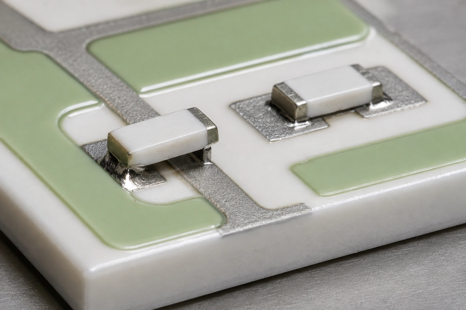
Tombstoning describes rotation that raises one end of a leadless component during soldering; partial lift can leave an incomplete connection without producing a fully upright part. Record when motion begins. A component displaced before reflow, a lead pulled during rework and a joint cracked after cooling require different investigations even if all produce an open circuit.
Identify the specific two-terminal component and fired pad construction. The chip body, its termination finish, the solder deposit and the ceramic metallization form the active assembly interface. Do not treat a printed resistor region as a movable chip component, and do not transfer an FR4 pad recommendation directly to a ceramic layout with different heat paths and overglaze openings.
Inspect the effective wetting regions at both ends
Map the component placement against both finished pad windows. Include metal concealed by the body, exposed toe regions, overglaze boundaries and the conductor connections leaving each pad. Equal artwork rectangles may not produce equal accessible regions after printing and placement variation. A component displaced along its axis can have different end overlap even when its center remains within a general placement box.
Compare thermal connections as well as visible area. One pad may connect to a broad conductor, terminal or local support while the other connects through a narrow neck. Such asymmetry can affect the temperature history during reflow. The ceramic's thermal conductivity alone does not establish equal end temperatures; the complete local structure and heating arrangement must be considered.
Record the order of melting, wetting and component motion
Where the assembly can be observed without changing its relevant boundary, capture a synchronized view of both ends during a representative heating trial. Distinguish solder melting from its subsequent spreading onto the termination, and identify the onset of chip rotation separately. A temperature crossing does not prove that wetting began at that instant.
Timing resolution must suit the claimed difference. At 60 frames per second, one frame spans about 0.0167 second. If each end's onset is located within one frame, a conservative difference uncertainty is about 0.0333 second. A reported 0.12-second wetting delay can be examined with that record, whereas a four-frame-per-second record cannot resolve it on the same basis. Preserve the frames and event definitions instead of reporting an unsupported exact delay.
Compare the paired deposits before they become fillets
Measure or inspect paste deposits before placement, retaining their position, height or volume and any offset relative to the pad. Total paste consumption for a panel cannot reveal whether the two ends of one component received different deposits. Keep aperture condition, release behavior and placement displacement associated with the specific component pair.
For an assumed pair with deposit volumes of 0.011 and 0.009 cubic millimeter, the difference is 0.002 cubic millimeter and the pair mean is 0.010. The difference divided by that mean is 20 percent. Define this convention explicitly: difference divided by the larger deposit would instead be about 18.18 percent. Neither number is a universal tombstoning threshold, and matching volumes alone does not ensure matching wetting timing.
Use a moment balance to organize the mechanism, not set a threshold
A force creates rotation according to its direction and lever arm about the current support or contact region. During reflow, solder menisci, component weight, paste tack and contact beneath the body can all contribute. The contact geometry changes as the component moves. A comparison of surface tension with component weight alone omits forces that may determine whether motion starts.
As a unit check, an assumed net upward force component of 20 micronewtons acting at a 0.6-millimeter lever arm produces 12 nanonewton-meters of moment. An assumed 0.4-milligram component has a weight of about 3.924 micronewtons; at a 0.3-millimeter arm its opposing weight moment is about 1.177 nanonewton-meters. These selected inputs illustrate scale and units only. The missing solder-contact and tack terms prevent the calculation from predicting lift.
M = Fperpendicular × lever arm; Mweight = m g × horizontal lever arm
- Moment M is in newton-meters; one nanonewton-meter is 10^-9 newton-meter.
- Fperpendicular is the force component perpendicular to the stated lever arm.
- m is mass in kilograms and g is gravitational acceleration.
Illustrative static moment components with specified directions and lever arms. Dynamic wetting geometry, underside menisci, tack and motion are not solved; no lift threshold follows.
Use orientation changes to locate the source of imbalance
Design comparisons that change one physical relationship at a time. Rotating a nonpolar component by 180 degrees relative to a marked pair of pads can help determine whether a consistent early-wetting end follows the component termination. Changing the assembly's orientation relative to heating can test whether the effect follows furnace direction. Keep these changes separate, and respect component polarity or mounting restrictions where present.
If the effect remains at the same artwork pad after component rotation, inspect that pad's thermal connection, exposure and deposit. If it reverses with the component, examine termination identity and handling. If it follows heating direction, evaluate shielding and local temperature history. These patterns guide the next experiment; none uniquely proves a cause without repeat observations and controlled material histories.
| Comparison | Keep fixed | Question isolated |
|---|---|---|
| Rotate an eligible nonpolar chip on the same pad pair | Artworks, deposits and heating orientation | Does early wetting follow a component end? |
| Rotate the assembly relative to heating | Component-to-pad orientation and material history | Does the event follow the heating direction? |
| Compare paired deposited volumes | Pad and component geometry | Does deposit imbalance correlate with the event? |
| Compare symmetric and asymmetric pad heat paths | Component lot, solder and agreed profile | Does local thermal connection change end timing? |
| Repeat with controlled termination condition | Geometry and deposited volume | Does surface condition explain different wetting behavior? |
Evaluate profile changes within the complete material window
An altered heating profile can reduce a thermal difference yet also change flux activity, wetting rate and exposure of the fired conductor. Do not assume that a longer soak or more active flux always improves the result. Select candidate changes within the compatible solder, component and metallization process conditions, and measure the local assembly response rather than relying only on oven settings.
For a simple crossing-time estimate, a three-kelvin end-to-end difference during an approximately linear 1.5-kelvin-per-second ramp corresponds to two seconds between reaching the same temperature. This does not predict a two-second wetting delay: melting behavior, surface condition and flux state still matter. Use the estimate to choose observation timing and sensor resolution, then compare it with the actual event sequence.
Verify both connection integrity and the retained ceramic interface
After the selected change, inspect both ends for partial lift and incomplete wetting, not only obvious upright components. Keep initial alignment, event observations and finished side views linked to the same specimen. Check the applicable electrical and attachment requirements, including whether the altered solder envelope reaches adjacent conductors or the overglaze boundary.
Retain the fired pad and ceramic condition after the evaluated thermal exposure. A process that prevents lift by increasing solder contact time may create a different metallization or substrate risk. The accepted result should identify the corrected imbalance, the controlled assembly configuration and the evidence that both joints form consistently without introducing another failure mechanism.
Provide the paired-pad reflow event record
Send the two ends together so placement, thermal history and wetting can be reviewed as one assembly event.
- Component construction, polarity restrictions, termination finish and marked orientation relative to both pads.
- Finished conductor and overglaze openings, pad connections, ceramic support and local thermal neighbors.
- Paired paste deposit observations, aperture details, placement coordinates and material history.
- Local thermal records and synchronized images identifying melting, wetting and first motion at each end.
- Controlled orientation or deposit comparisons, finished joint views and electrical or attachment results.
The drawing-upload form loads as you reach this section.