
On this page
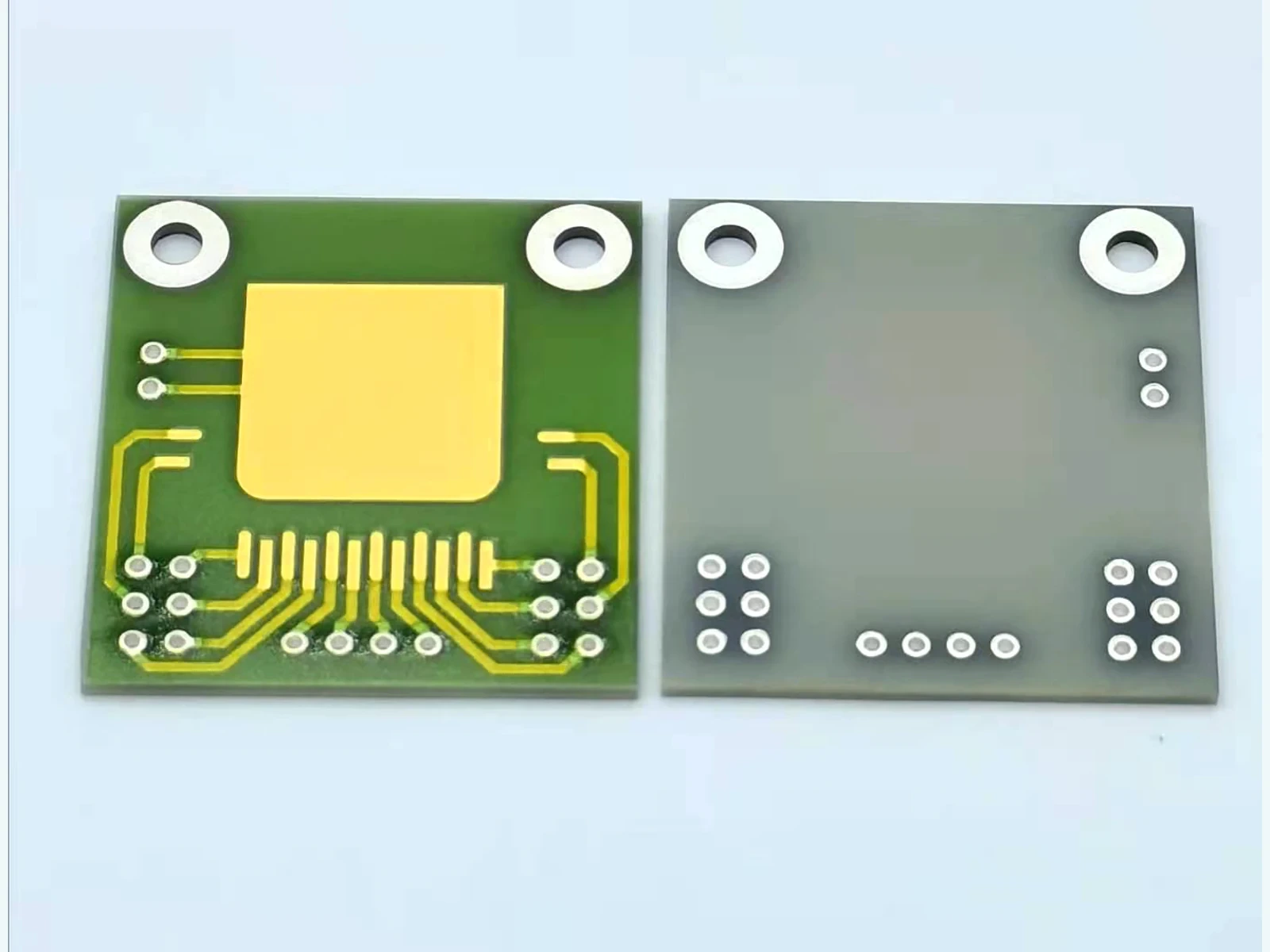
When a ceramic circuit loses most of its heat through edge clamps, the useful conduction area is the cross-section leading toward those clamps, not the broad face of the substrate. A centrally heated strip can send heat in two directions, and the two paths need not carry equal power. This calculation method defines those lateral branches, includes the clamp interfaces and shows which measurements are needed before an edge-cooled arrangement can be assessed.
Key design decisions
- Identify the source-region boundary and each real clamp contact; the unsupported distance, strip width and ceramic thickness define the lateral path.
- Use a two-branch model only when the source region can be represented by a common temperature and losses through the broad faces are sufficiently small or separately accounted for.
- Measure both clamp temperatures and contact conditions; geometric symmetry does not establish equal heat flow when the surrounding assembly is asymmetric.
Verify that the installation is actually edge cooled
Mark the surfaces through which heat can leave the installed circuit. A back face suspended above a housing is different from one bonded to it. Leads, mounting hardware, air and neighboring components can provide additional paths. Establish whether edge conduction dominates at the evaluated power and orientation before assigning all generated heat to the clamps.
Define the source region separately from the intervening strip. The branch model starts at an approximately isothermal source boundary and ends at a named sink boundary. If a small die injects heat into only part of the width, the local spreading between the die and that boundary needs its own treatment. The branch result does not predict the die temperature automatically.
Record the clamp contact width and its position, not just the outside dimensions of the bracket. A nominally wide clamp touching only two small high points does not create a uniform cooled edge.
Calculate resistance along the unsupported ceramic
For a uniform unheated strip between the source boundary and clamp, the lateral conduction area is strip width multiplied by ceramic thickness. Length is measured along the heat path. Apply the steady conduction relation to each branch and combine the defined branch resistances using the stated series or parallel connection.
Add the resistance of the ceramic-to-clamp interface and any included path inside the clamp to the same branch. State where the sink temperature is defined so these contributions are not omitted or counted twice. If temperature is measured directly at the clamp contact surface, a remote housing resistance beyond that surface is outside this particular branch.
Do not use the complete plan area of the board in the denominator. That area is perpendicular to through-thickness flow, whereas heat approaching an edge crosses a much smaller section. Confusing those areas can make an edge-cooled design appear unrealistically effective.
Ri = Li/(ki wi t) + Rc,i; Qi = (Ts − Ti)/Ri
- Ri: total resistance of lateral branch i, in K/W.
- Li: unsupported conduction length from the source boundary toward clamp i, in m.
- wi and t: effective strip width and ceramic thickness, in m.
- ki: conductivity appropriate to that material and temperature, in W/(m·K).
- Rc,i: interface and clamp contributions inside the selected boundary, in K/W.
- Ts and Ti: source-boundary and branch sink temperatures; Qi is heat flowing toward that sink, in W.
Steady, approximately one-dimensional conduction in each unheated branch; constant properties over the evaluated range and an approximately uniform source-boundary temperature.
Check the symmetric two-clamp case first
When equal branches terminate at the same sink temperature, their conductances add. Each carries half the source power, and the equivalent resistance is half one branch resistance. This is a useful check on a spreadsheet: connecting a second identical sink should not double the predicted resistance.
Consider an assumed strip width of 10 mm, thickness of 0.8 mm and unsupported length of 15 mm on each side. With an assumed conductivity of 24 W/(m·K), each ceramic branch has a resistance of 78.125 K/W. Neglecting the contacts for this arithmetic exercise, the pair gives 39.0625 K/W. A 0.5 W source therefore raises the common source boundary by approximately 19.53 K above the equal clamp temperatures.
These assumed inputs demonstrate the calculation, not a material rating or product recommendation. If only one of those modeled paths remains effective, the predicted rise doubles to approximately 39.06 K under the same idealized conditions. Re-evaluate other heat losses and actual contact behavior before interpreting a real one-clamp experiment.
Solve unequal sink temperatures without averaging them
For unequal branches, conserve energy at the source node. The generated power equals the sum of the signed branch flows. Solving that balance gives the source temperature from each branch conductance and sink temperature. An ordinary arithmetic average of clamp temperatures is valid only for equal conductances.
As an independent network exercise, take a left branch of 40 K/W ending at 25°C, a right branch of 80 K/W ending at 35°C, and source power of 0.75 W. The calculated source node is 48.33°C. Approximately 0.5833 W leaves through the left branch and 0.1667 W through the right, adding to the applied 0.75 W.
If one sink becomes hotter than the calculated source node, its branch flow is negative: that structure supplies heat to the circuit rather than removing it. Retain the sign in the energy balance. Clipping negative flow to zero would conceal external heating from a hot enclosure or adjacent assembly.
Ts = [Q + Σ(Ti/Ri)] / Σ(1/Ri); Q = ΣQi
- Q: heat introduced into the common source node, in W.
- Ti/Ri: conductance-weighted contribution from sink i.
- The summation includes every lateral branch represented in this reduced network.
Every branch is connected to the same source-temperature node. Sink temperatures are measured or independently specified, and additional source or loss terms must be included explicitly.
Keep interface improvement separate from clamp loading
A lower contact resistance may reduce source temperature, but increasing clamp force is not a universal correction. Contact area, flatness, interface material and ceramic support all affect the installed state. Use the mechanical requirements of the actual substrate and fixture; do not infer an allowable force from this thermal calculation.
Inspect whether the ceramic is supported where load enters it. A clamp can improve thermal contact while bending an unsupported region or loading an edge defect. Check stress concentration and differential material expansion whenever a thermal experiment changes the mechanical arrangement.
For a contact comparison, preserve the ceramic, source, sensor positions and clamp-temperature boundary. Record any change in contact width or insulating layer as well as the applied assembly condition. A cooler circuit does not isolate contact resistance if the alteration also moved the sink closer to the source.
Choose a comparison that identifies the weak branch
Use observations from both sides of the circuit, not a source temperature alone. A source reading can fit several combinations of contact and branch resistance. Changing one known boundary and observing the response provides more information than fitting every unknown to a single operating point.
| Observation or question | Controlled comparison | Interpretation boundary |
|---|---|---|
| Left and right clamps differ in temperature | Measure both sinks while keeping power and attachment fixed | A temperature difference can change the heat split without any ceramic defect |
| A contact change lowers the source temperature | Return to the original contact arrangement and repeat | Reversibility helps separate interface behavior from permanent specimen change |
| The source runs hotter than the branch estimate | Inspect source spreading, actual contact width and included interfaces | Do not adjust conductivity solely to force agreement |
| Airflow strongly changes the measured rise | Compare at fixed clamp temperatures and electrical power | Broad-face convection may be too important to omit |
| Results differ after remounting | Record contact position, flatness and sensor attachment | Mechanical repeatability is part of the thermal boundary |
Measure the nodes and test the model's limits
Place temperature sensors at the boundaries used in the calculation and document how they are attached. A sensor on a remote bracket does not necessarily represent the ceramic contact temperature. Verify that sensor wires do not create a significant extra heat path, especially when the source power is small.
Measure the heat-generating electrical input separately from lead losses outside the source region. Record temperatures over time and use a defined steady criterion. Applying the steady branch equation during warm-up assigns stored energy to conduction and can produce a misleading apparent resistance.
Escalate to a spatial or transient model when the strip widens sharply, contains holes, has distributed heating, or exhibits substantial temperature variation across its width. Nearby heated components may require additional source nodes. Material conductivity may also vary with temperature. These conditions should change the model structure or inputs, not be hidden in a fitted universal clamp factor.
Deliver a branch model that another engineer can reproduce
Provide a drawing showing the source boundary, branch lengths, width changes, ceramic thickness, clamp contact regions and temperature-sensing points. Attach the assumed material conductivity and the temperature interval to which it applies. Report ceramic and interface contributions separately, together with the resulting heat split.
Evaluate the demanding installation states as well as the symmetric example: unequal housing temperatures, reduced contact area or an added nearby heat source. Use project-defined conditions rather than inventing a failure severity. Keep the maximum allowable source and joint temperatures as independent requirements to compare with the calculated and measured results.
The output is a decision about this lateral cooling arrangement: shorten a branch, increase its section, improve a controlled interface, or choose another cooling architecture. It is not a substitute for a general heat-spreading calculation or proof that edge mounting is suitable for every ceramic circuit.
Provide the edge-cooling boundary conditions
Send the clamp layout and thermal measurements so the lateral branches can be evaluated independently from source spreading and through-face cooling.
- Ceramic outline, thickness, unsupported distances and actual edge-contact widths.
- Heat-source footprint, electrical power and whether neighboring sources operate simultaneously.
- Clamp temperatures, sensor positions, interface materials and mechanical support arrangement.
- Observed source-temperature traces and remounting or boundary-change comparisons.
- Permitted source and interconnect temperatures under the specified installation states.
The drawing-upload form loads as you reach this section.