
On this page
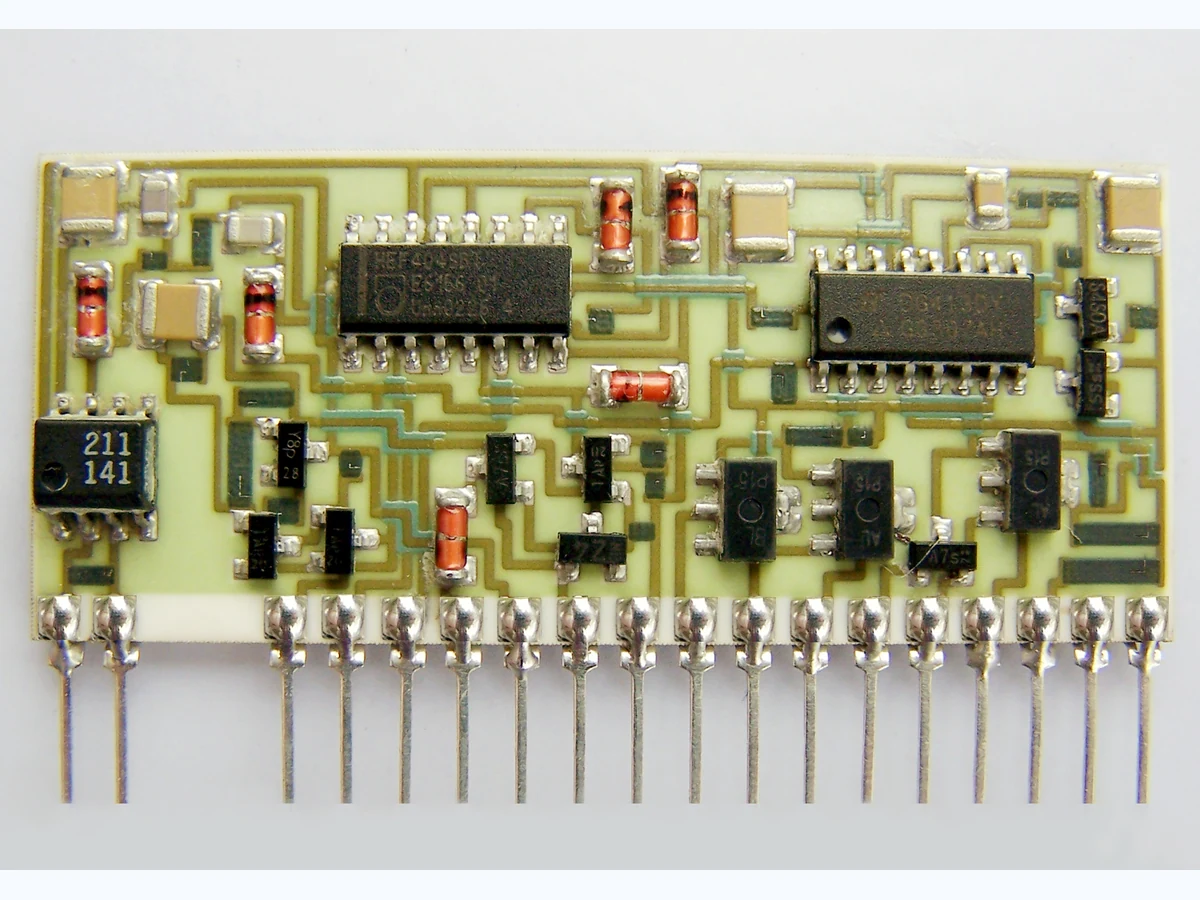
A ceramic hybrid module is assembled through a sequence in which each operation changes access for the next. A tall component can block a wire-bond tool, coating can cover a test point, and early enclosure can hide contamination or damage. The best sequence is not simply lowest-temperature first or all soldering before bonding. It is the order that preserves required access, material compatibility, inspection and rework while controlling cumulative exposure. This page owns sequence selection; package design, individual attachment processes and panel separation remain separate technical owners.
For a drawing-specific part, review the Custom thick film ceramic circuits construction, product evidence and quotation inputs alongside this method. Prepare the dfm checklist with your operating conditions.
Key design decisions
- Map tool, vision, cleaning, probe and rework access for every operation.
- Build a precedence network from physical and material constraints.
- Track cumulative heat, contamination and mechanical handling by component.
- Validate critical transitions on representative modules before release.
1. Inventory operations and the state each one creates
List substrate cleaning, incoming inspection, die attach, passive attachment, cure or reflow, wire bonding, connector or lead attachment, cleaning, electrical test, coating, encapsulation, lid or housing installation and final test only as applicable to the actual module. For each operation, record incoming cleanliness, supported surfaces, tool clearance, temperature/atmosphere, materials added, force and the features concealed afterward. Do not add an operation merely because it is common in another hybrid process.
Define the output state in inspectable terms. After die attach, for example, record placement, visible fillet or boundary, bondline evidence and exposed bond pads. After wire bonding, record loop envelope and bond access. A process complete label is less useful than a state description that tells the next operator what remains accessible and what must already have been accepted.
2. Draw access volumes above and around the ceramic
Model the swept volume of placement tools, bond heads, probes, dispensers, cleaning flow, inspection optics and rework tools. Include approach angle, stand-off, fixture walls, neighboring component height and cable or lid obstructions. Two components can fit in the final module yet prevent each other's assembly. The access map should show the state in which each operation occurs, not only the completed three-dimensional envelope.
Mark fragile and no-contact regions on the ceramic, including printed resistors, trimmed areas, wire loops, exposed die surfaces and glass edges. A fixture that was safe for a bare substrate may touch a populated module when it is inverted. If an operation requires backside support, define where that support can contact after front-side features are present. Preserve access for required inspection rather than assuming final electrical test can replace every intermediate observation.
3. Convert access and chemistry into precedence constraints
Write each compulsory relationship as A before B with a physical reason. Wire bonding may need to precede placement of a tall adjacent component because the bond tool loses approach clearance. Cleaning may need to precede an absorbent or moisture-sensitive material. A coating must follow inspection of the surfaces it conceals. A component that cannot tolerate a later reflow may need to be attached after that thermal operation, but its attachment must then be compatible with existing structures.
Use a directed acyclic graph to expose contradictions. If operation A must precede B for access, B must precede C for chemistry, and C must precede A for temperature, there is no feasible simple sequence. The design, material or fixture must change. Do not resolve the contradiction by silently ignoring one constraint. Record optional preferences separately from mandatory precedence so scheduling convenience does not acquire the status of a technical requirement.
4. Compare feasible sequences by risk-weighted access loss
After mandatory constraints produce feasible orders, rank them using visible project factors: number of critical operations performed with restricted access, cumulative heat on sensitive parts, contamination transfers, handling/inversion events, and rework blocked before final test. Assign weights only with project ownership and keep each underlying count. The score supports discussion; it does not predict yield or reliability.
For illustration, sequence A has two restricted-access operations weighted 4 each, one additional thermal exposure weighted 3 and two inversions weighted 1, giving S = 2×4 + 1×3 + 2×1 = 13. Sequence B has one restricted operation, two thermal exposures and one inversion, giving 11 with the same selected weights. The difference is meaningful only if both sequences satisfy mandatory constraints and the weights reflect this module's consequences.
Ssequence = sum(waccess × Naccess) + sum(wthermal × Nthermal) + sum(wcontam × Ncontam) + sum(whandling × Nhandling)
- N terms count defined sequence burdens for the candidate order.
- w terms are project-agreed consequence weights.
- Mandatory precedence violations are not scored; they make the sequence infeasible.
Transparent ranking aid, not a manufacturing yield model or universal assembly rule.
5. Track cumulative exposure by material and component
Create a ledger for every die, passive, printed film, attachment, wire bond, coating and connector. Record each later temperature cycle, cleaning chemistry, atmosphere, moisture hold, mechanical clamp, inversion and permitted rework. A component's data-sheet process limit must be interpreted for the actual duration, ramp, atmosphere and mounted state. Do not assume that separate exposures below a headline maximum are harmless in combination.
Connect the ledger to evidence. A cured adhesive may experience a soldering step; a fired conductor may experience multiple assembly heat cycles; a cleaned surface can be recontaminated by dispensing or handling. Where compatibility is uncertain, use representative material stacks and controls. Keep fired thick-film processing distinct from later polymer curing and solder assembly rather than referring to all of them simply as heat treatment.
6. Reserve inspection and rework at the point of best information
Place inspection immediately after the operation whose result it must discriminate and before another step hides or changes that evidence. Test die-attach position before surrounding components block the view; inspect bonds before coating; verify sensitive resistors before and after exposures relevant to drift. Intermediate tests should isolate operations, not merely repeat final continuity without diagnostic value.
Define the last responsible rework point. Rework performed after wire bonding, coating or enclosure can damage good structures and add unrecorded heat or contamination. If a non-reworkable operation occurs early, increase the evidence required before crossing it. If a test point must remain through final assembly, reserve its mechanical and electrical access in the module design.
| Operation | Access needed | Evidence before concealment | Reopening concern |
|---|---|---|---|
| Die attach | Placement/dispense and thermal path | Position and interface record | Later heat or die movement |
| Passive attach | Placement and joint inspection | Component identity and joint state | Reflow/rework exposure |
| Wire bonding | Tool approach and loop volume | Bond and loop inspection/test | Coating, lid or handling damage |
| Cleaning/coating | Flow, drainage and masked access | Cleanliness and coating boundary | Trapped residue or blocked pads |
| Housing/lid | Support and perimeter access | Pre-close electrical/visual record | Hidden defect and destructive rework |
7. Validate sequence transitions and read failure timing
Run representative modules through the proposed order while retaining identifiers and records at each gate. Include the actual fixtures, waits, cleaning, atmosphere and handling. At critical steps, keep witness structures or process controls that separate heat, chemistry and mechanical handling. Measure selected electrical values at stable, stated conditions so temperature recovery is not mistaken for permanent change.
A value shift first appearing after cleaning focuses investigation on moisture, residue, handling or measurement state; a shift after cure or reflow focuses on thermal and material interaction. Bond damage appearing only after housing installation points to clearance, support or handling. Contamination found beneath a coating may have existed before coating or been introduced during dispense, so review the immediately preceding record. Preserve the first detected state rather than repeatedly processing the failed module before examination.
8. Release the sequence as a controlled dependency network
The release record should contain the operation list, mandatory precedence reasons, access volumes, fixture contacts, exposure ledger, intermediate inspections, rework boundaries and pilot evidence. A change to component height or location, attachment material, tool, fixture, cleaning, thermal profile, coating, test access, housing or rework policy reopens affected dependencies. The printed traveler should preserve operation identity and required evidence, not only a numbered list.
For quotation, send the populated module drawing, bill of materials with relevant handling constraints, ceramic artwork, package interface, candidate assembly operations, required inspections and permitted rework. Identify processes that are customer-mandated versus open to supplier review. This enables a feasible manufacturing proposal without claiming that the proposed order proves production capability, reliability or compatibility before representative validation.
Send the access-sensitive assembly package
Provide the module geometry, material constraints and test gates needed to build a feasible operation sequence.
- Ceramic artwork, populated assembly drawing and package interface
- Component dimensions, sensitive surfaces and attachment requirements
- Thermal, atmosphere, cleaning and handling limits with source documents
- Tool, fixture, probe, optical and rework access envelopes
- Required intermediate/final inspections and electrical test points
- Prototype quantity, permitted substitutions and acceptance owner
The drawing-upload form loads as you reach this section.