
On this page
Changing the support span of a ceramic breakout fixture can change both the bending moment and the displacement required to separate a panel. The direction of that change depends on whether force or travel is being controlled. A useful calculation therefore begins with the fixture's actual boundary conditions, not a rule that a shorter span is always safer. The model supports a controlled comparison of one breakout operation; local contact damage and the real fracture path still require physical evaluation.
Key design decisions
- Identify the support contacts, loading point and controlled quantity before comparing fixture settings.
- Use an elastic beam estimate only for the intact, slender region that reasonably matches its assumptions.
- Separate nominal bending stress from scribe-root concentration, contact damage and the final fracture criterion.
Draw one operation as a load path
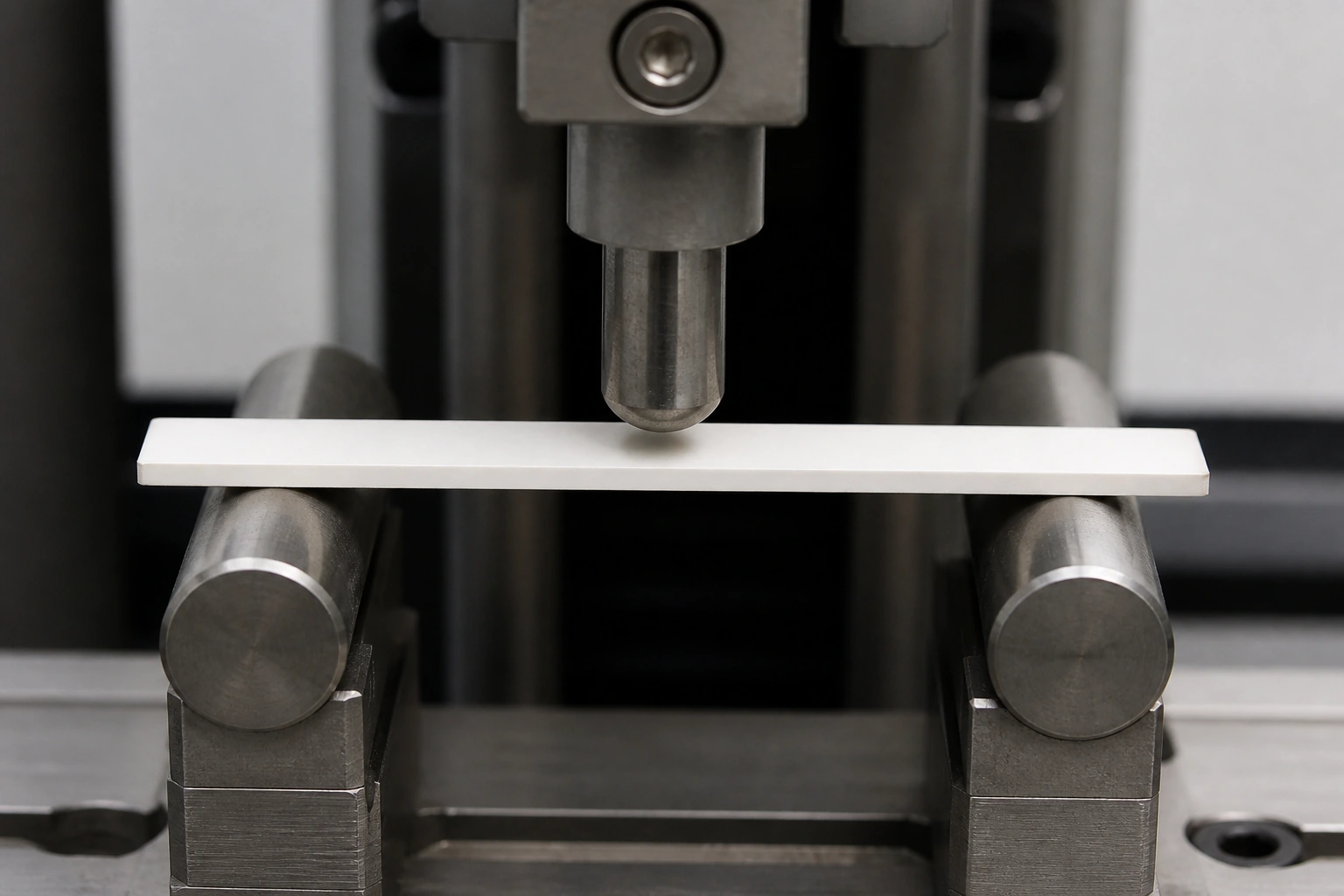
Identify the two support contacts, their separation, the applied load and the ceramic region between them. A broad panel resting on a flat nest is not automatically a simply supported beam. Friction, extra contact points, warped surfaces or a clamped edge can add constraints that the elementary calculation does not include.
Record which face contains the scribe and which face is in tension during loading. Define the intended fracture line relative to the contact centers. An off-center tool does not create the same bending moment distribution as a centered tool, and a flexible support can move the effective contact location as force increases. Photograph or dimension the loaded arrangement rather than relying on the nominal fixture drawing alone.
Compare spans under the same applied force
For a slender, rectangular, homogeneous beam with two simple supports and a centered transverse force, the largest bending moment occurs beneath the loading point. Combining that moment with the rectangular section property gives a nominal outer-fiber stress. This is a useful sensitivity model for a matched, intact region before fracture, not a local crack-tip stress calculation.
At equal force and unchanged section dimensions, increasing support span increases the nominal bending stress. Increasing thickness has a stronger effect because thickness is squared in this expression. Do not insert a supplier's flexural-strength typical into the equation and present the resulting force as a safe machine limit: specimen surface, flaws, scribing, contact geometry and statistical strength variation are not represented.
Mmax = FL/4; σnom = 3FL/(2bt²)
- F is the centered transverse force, L the contact-to-contact support span, b the beam width and t the intact section thickness.
- Mmax is the largest elastic bending moment and σnom the nominal outer-fiber bending stress in the idealized section.
Small deflection, slender beam, linear elasticity, simple supports and a centered load. These equations do not describe a scribe notch, plate behavior, crushing contact or crack propagation.
Do not transfer the force conclusion to fixed travel
A displacement-driven tool presents a different comparison. For the same idealized beam, the midpoint deflection is FL³/(48EI), where E is elastic modulus and I is the section second moment. Rearranging shows that the force needed for a fixed elastic deflection changes strongly with span. The instruction to reduce span while retaining the same machine travel can therefore increase the reaction force.
The tool's displayed travel may include frame compliance, support indentation, clearance take-up and motion after separation. Measure or bound those contributions before assigning all travel to ceramic bending. Once a crack grows, the intact elastic relationship no longer describes the operation. A travel stop and a force limit address different risks and should not be treated as interchangeable settings.
Keep local contact and scribe effects outside the beam shortcut
The scribed ligament is a deliberate local weakness. Its root shape, continuity and nearby defects can dominate crack initiation. Substituting a guessed remaining thickness into an intact-beam formula does not reproduce that local stress field. The resulting number may be useful only as a clearly stated comparative index, never as a fracture prediction.
Support tips and loading noses introduce another local condition. A small hard contact can damage the ceramic or a printed layer even when the nominal span calculation looks acceptable. Check contact position, nose geometry, cleanliness and whether compliant protection changes location under load. Material brittleness makes impact and concentrated tension important, but the correct fixture geometry remains specific to the panel.
Choose the comparison from the controlled variable
Use a short fixture matrix to prevent apparently similar trials from answering different questions. Change one primary boundary at a time where practical, and record what was held constant. A lower peak reading is not automatically a better result if it comes with a different crack path or more edge damage.
| Comparison | Nominal prediction | Additional observation |
|---|---|---|
| Longer span at equal force | Higher idealized bending moment | Confirm contact centers and check fracture location |
| Shorter span at equal ceramic deflection | Higher required elastic force | Separate frame travel from actual panel deflection |
| Different loading-nose geometry | Simple beam moment may remain similar | Inspect local crushing, film contact and slip |
| Different panel width or holes | Rectangular beam section may no longer apply | Review plate action and interrupted load paths |
| Same setting after an earlier break | Support and stiffness may have changed | Re-establish the actual boundary for the smaller piece |
Relate force and travel to the observed separation
Retain synchronized force and travel records when the equipment and trial permit them. Identify initial contact, elastic loading, first separation and subsequent motion. These events can overlap, and an apparent peak may reflect fixture slip rather than the intended break. Keep the raw trace linked to the specific panel position and operation.
Inspect immediately after the defined separation and again after the planned handling step. This distinguishes a crack created during breakout from an edge chip introduced when the piece falls into a tray. Record the fracture direction and location relative to the scribe and supports. Do not remove unusual traces solely because they make the average less tidy; they may reveal an unstable contact condition.
Use tolerance ranges to choose the next trial
Run the nominal comparison over the drawing's actual thickness and span ranges. State which dimensions are measured and which are assumed. If the model's ranking changes across plausible contact positions, resolve the contact geometry before optimizing a force setting. Uncertain boundary conditions can overwhelm a precise thickness measurement.
For panels with slots, large holes, populated areas or a width that is not small relative to span, seek a more suitable mechanical model or direct fixture comparison. Keep the simple estimate as a transparent baseline. Its value is revealing sensitivities and missing inputs, not making a complicated panel look mathematically certain.
Release the load condition with the fixture revision
The resulting instruction should identify support spacing, contact surfaces, loading direction, force or travel control, part orientation and the condition used for evaluation. Include the allowed panel state and the inspection method for the separated piece. A fixture revision that moves a support changes the mechanical condition even if the electrical artwork is unchanged.
Keep this calculation separate from the broader choice of row-first or column-first break sequence. The sequence defines which piece arrives at the fixture; this review establishes what happens when that particular piece is loaded. Linking the two decisions produces a reproducible operation without repeating a general singulation checklist.
Provide the breakout load and support arrangement
Send the information needed to compare fixture mechanics for one defined separation operation.
- Panel material and dimensions, scribe orientation, openings and the geometry of the piece at this stage.
- Support contact spacing and shape, loading-nose location, protected faces and part orientation.
- Force or travel control mode, fixture compliance information and available load-displacement records.
- Identified fracture locations, edge observations, printed-layer condition and final dimensional requirements.
The drawing-upload form loads as you reach this section.