
On this page
A lifted overglaze edge can expose an underlying conductor, interfere with an assembly operation or generate loose fragments. The visible lifting does not reveal which interface failed. Separation may occur beneath the glass, within the glass, within an underlying printed layer or in another part of the stack. Locating that plane is the first useful step toward a correction; increasing thickness or cleaning more aggressively before understanding it can change the problem instead of resolving it.
Key design decisions
- Preserve the lifted fragment and the underlying surface with their original orientation whenever practical.
- Map the failed region against the actual layer stack, opening boundaries and nearby conductor steps.
- Choose a corrective trial from the observed failure plane rather than treating all edge lifting as contamination.
Draw the local stack at the lifted boundary
Identify whether the overglaze edge ends on bare ceramic, conductor, resistor or a previously fired dielectric. A single protective patch can cross several of these surfaces, so its perimeter does not necessarily share one interface condition. Mark the material transitions and the local print sequence on the failure map.
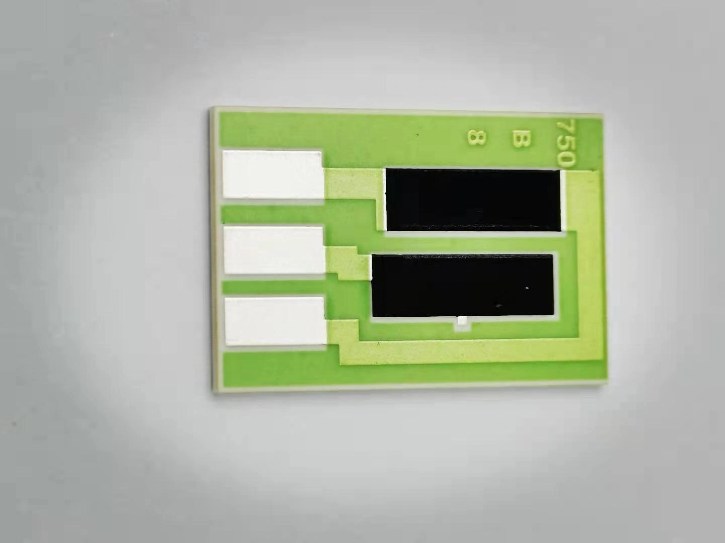
Retain the exact overglaze identity and its supported material combinations. Glass appearance alone does not establish compatibility with every underlying conductor or resistor. A glossy green finish describes the visible state, while the interface depends on the selected formulation and processing route. Do not transfer one material's firing or compatibility instructions to another merely because the colors match.
Keep both sides of the separation available
Photograph the lifted region before touching it, including the surrounding edge and orientation marks. If a fragment detaches during a controlled examination, retain it without rubbing or cleaning the mating surface. The underside can show material that is difficult to identify from the ceramic side alone.
Record when the separation was first observed relative to firing, handling, cleaning, trimming and attachment. An observation after cleaning does not prove cleaning initiated the defect; the operation may have revealed an existing weak region. Conversely, a pre-cleaning image showing an intact edge does not establish an undamaged subsurface interface. Preserve the sequence without converting timing alone into a cause.
Distinguish interface separation from fracture within a layer
If glass remains attached to both sides of a separated region, fracture within the glass may be involved. If a fragment carries underlying metallization, the failed plane may lie beneath that metallization rather than at the glass surface. These observations guide the investigation, but material identification and section geometry must be reliable before a failure mode is assigned.
Mechanical tests also fail at the weakest part of their complete loading arrangement. A test adhesive, attachment stud or substrate can fail before the overglaze interface of interest. A peak force without a failure-plane record therefore cannot be called overglaze adhesion. Select a method appropriate to the small brittle multilayer specimen rather than borrowing a coating test limit from another substrate system.
Report edge involvement separately from affected area
Edge lifting is spatially concentrated, so an area fraction can hide its relation to a critical opening or protected conductor. Record affected perimeter length, inward extent and the nearby function separately. A small lifted area beside a bond opening can be more consequential than a larger cosmetic irregularity far from a functional feature.
For an illustrative rectangular protected region measuring 20 by 6 millimeters, the total perimeter is 52 millimeters and the nominal area is 120 square millimeters. If the observed lift involves 2.6 millimeters of perimeter and 0.2 square millimeter of area, the corresponding fractions are 5 percent of perimeter and about 0.167 percent of area. They describe different geometry; neither is a universal acceptance threshold.
edge fraction = L_affected / L_perimeter; area fraction = A_affected / A_protected
- Lengths are measured on the stated overglaze boundary using matching units.
- Areas use the same plan-view projection and matching square units.
- The fractions summarize extent but do not identify failure plane, severity or protective function.
A defined boundary and consistently segmented images. The numerical example uses a rectangle without additional internal openings; real opening perimeters must be identified explicitly.
Use the observed plane to choose the next comparison
Do not start with a universal cleaning correction. Some separations may involve an interface preparation problem, while others originate in the glass body or an underlying layer. A targeted comparison should alter the suspected contributor while keeping the remaining stack and thermal history representative.
| Observed evidence | Primary question | Focused next comparison |
|---|---|---|
| Separation appears at glass-to-bare-ceramic boundary | Was that local ceramic interface formed consistently? | Matched surface preparation and handling histories with the same glass route |
| Lift follows a conductor step | Does local geometry or layer coverage control the failure? | Oriented sections across the step and comparable flat regions |
| Underlying metal leaves with the glass fragment | Did the conductor-to-substrate region fail? | Identify the fracture surfaces and review the conductor's formation history |
| Glass remains on both mating surfaces | Is fracture within the glass involved? | Examine local thickness, defects and the loading or thermal sequence |
| Only a later cleaning or attachment group shows lifting | Which added exposure reveals or creates the weakness? | Before/after specimens and a controlled omission or matched exposure group |
| Test fixture or adhesive fails first | The intended interface was not measured to failure | Revise the test interpretation or specimen method without reporting false adhesion strength |
Test a preparation hypothesis without assuming its cause
When surface contamination is suspected, preserve an untreated failed specimen and compare a defined preparation route on matched samples. Keep the interval between preparation and overglaze application recorded. A treatment that changes roughness, chemistry and handling at once may improve the outcome but cannot isolate which change mattered.
Use a suitable analytical method if identifying the transferred material is essential. An image that looks clean does not prove the absence of a thin film, and a broad elemental scan may not resolve a small amount of residue. State the method's detection question and specimen preparation. Avoid naming a contaminant from appearance alone or assigning it to a particular process without supporting evidence.
Separate local geometry from whole-panel processing
Compare equivalent edge types across the panel rather than mixing bare-ceramic edges, conductor steps and opening corners into one defect count. If one geometry dominates, preserve that geometry in the corrective trial. A broad flat witness may pass while the constrained product edge continues to lift.
Record local layer thickness where it matters, not only an average on a large flat region. A thicker nominal deposit can alter the opening and local geometry, so it is not automatically a safer protective layer. Keep the intended resistor and conductor electrical measurements through the same processing sequence; a mechanical improvement must not conceal an unacceptable electrical shift.
Verify restored function and fragment control
After a correction, assess the same boundary locations and the functions they protect. Confirm that connection openings remain usable and that the revised glass does not intrude into moving contacts or assembly access. Where detached fragments are a concern, the inspection and handling method should address that risk rather than merely improving the photograph.
Retain the original failure plane, revised process condition, local images and any relevant mechanical or electrical evidence in one record. Define which changes require renewed review, including another underlying paste, surface treatment or downstream exposure. A sound correction explains why the original boundary separated and demonstrates the intended final stack, without implying a general adhesion capability from a single attractive sample.
Provide the lifted-edge evidence package
Send the local stack and paired failure-surface observations needed to identify the separating interface.
- Overglaze and underlying-layer identities, local cross-section drawing, edge and opening locations.
- Original images, detached fragments where available, observed material on both sides and first-detection stage.
- Printing, firing, cleaning, handling and attachment histories with matched unaffected specimens.
- Affected perimeter and area definitions, functional consequences and proposed controlled comparisons.
The drawing-upload form loads as you reach this section.