
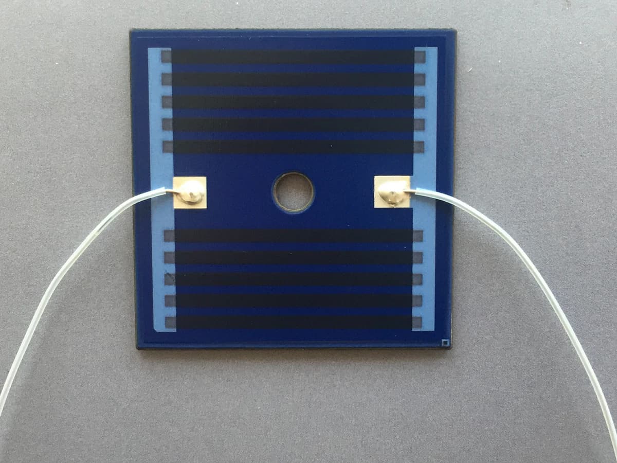
Overview
Alumina and stainless steel can both support printed-heater concepts, but they do not create the same electrical, thermal, or mechanical system. Alumina is itself electrically insulating, while a stainless-steel route depends on a compatible dielectric barrier between the resistive circuit and the metal. The useful comparison therefore follows the complete stack, heat path, mounting method, terminal interface, environment, and validation plan rather than a generic material ranking.
Engineering review matrix
Each row links a design variable to evidence that can support a drawing or release decision.
| Variable | Control question | Verification route |
|---|---|---|
| Electrical isolation architecture | Define working and transient electrical stress, grounding, accessible metal, dielectric layers, creepage paths, edge conditions, and the applicable system safety boundary. | Review the complete sectioned stack and test the production-intent construction under an agreed insulation method and conditions. |
| Heat-transfer path | Specify the heated load, contact area, interface material, pressure, flow or convection, insulation, heat sink, and temperature-sensor locations. | Correlate a thermal model or design estimate with temperature mapping in the actual mounting arrangement. |
| Temperature field and duty | Record setpoint or required surface profile, warm-up, steady state, cycling, standby, ambient extremes, and loss-of-load or dry conditions. | Use time-resolved measurements at defined locations and repeat the relevant duty and fault sequences. |
| Thermo-mechanical strain | Compare substrate expansion, printed layers, joining materials, clamps, housing, load, temperature gradients, and repeated cycles. | Inspect for cracking, distortion, delamination, resistance shift, and joint damage after representative thermal and mechanical exposure. |
| Geometry and mounting | Define outline, thickness, flatness, holes, formed or unsupported regions, edge support, clamp load, sealing surfaces, and assembly tolerances. | Measure the released datums and assemble tolerance-condition samples without forcing the heater into an unreviewed shape. |
| Printed material stack | Identify substrate surface, conductor, resistor, dielectric or overglaze, sequence, refires or cures, interfaces, and supplier compatibility evidence. | Review named material documentation and qualify the complete processed stack rather than transferring typical data between routes. |
| Terminals and assembly process | Define pads, connectors, welds, solder or adhesive, strain relief, assembly temperature, current path, sealing, cleaning, and rework. | Inspect and electrically test joints before and after the relevant assembly, cycling, pull, vibration, or environmental sequence. |
| Environment and protection | State moisture, fluid, scale, chemicals, cleaning, contamination, corrosion, vibration, and touch or abrasion exposure at each interface. | Expose production-intent samples to the agreed media and conditions, then compare electrical, thermal, visual, and mechanical baselines. |
Controlled model
Same-boundary substrate and heater-stack comparison
Compare the two routes at the same electrical input, heated load, contact stack, ambient, duty, sensor locations, and acceptance limits. The equations are screening models; material-property tables and a free-air sample do not release a finished heater.
P = V I = I² R = V² / RRelates electrical input power to the applied voltage, current, and heater resistance.
- Units
- P in W; V in V; I in A; R in Ω
- Use boundary
- Use the resistance at the relevant temperature and operating state. This equation does not predict surface temperature, warm-up time, or uniformity.
θ_layer = t / (k A)First-pass thermal resistance of one uniform layer normal to the heat-flow direction.
- Units
- θ_layer in K/W; t in m; k in W/(m·K); A in m²
- Use boundary
- Valid only for an approximately one-dimensional, uniform path with known contact area. Spreading, edges, interfaces, fluid flow, and local heater geometry need a fuller model or test.
ΔT ≈ P θ_thEstimates steady-state temperature rise across a defined lumped thermal path.
- Units
- ΔT in K; P in W; θ_th in K/W
- Use boundary
- A steady-state screening relation only. It does not cover transient warm-up, nonuniform temperature fields, changing convection, dry-run conditions, or fault control.
Decision comparison
| Decision | Route A | Route B | Verification |
|---|---|---|---|
| Electrical isolation architecture | Alumina is electrically insulating as a bulk ceramic, while surfaces, edges, terminals, mounting hardware, and contamination still belong to the insulation review. | Stainless steel is conductive and requires a compatible dielectric layer, controlled coverage, edge design, grounding, and the rest of the insulation system. | Review a sectioned production-intent stack and apply the project-selected insulation, leakage, and withstand methods under stated conditions. |
| Heat-transfer path | The ceramic body, printed layers, interfaces, contact pressure, and brittle-part support define the useful path into the load. | The metal spreader, dielectric layer, printed layers, interfaces, formed geometry, and grounding arrangement define the useful path into the load. | Compare modeled and measured temperature maps with identical load, mounting, ambient, duty, and sensor locations. |
| Mechanical response | Review brittle fracture, edge and hole condition, flatness, clamp load, and expansion mismatch across the printed and joined stack. | Review forming or flatness, plate distortion, dielectric and printed-layer strain, mounting load, and expansion mismatch. | Inspect the released assembly before and after representative mechanical and thermal cycling; do not infer performance from substrate identity alone. |
| Process and terminal compatibility | Use a named ceramic, resistor, conductor, protection, firing, and terminal system with recorded refires and assembly heat. | Use a named steel surface, dielectric, resistor, conductor, protection, firing or curing, grounding, and terminal system. | Qualify each complete material stack separately and retain supplier scope, process history, joint inspection, and electrical correlation. |
- Supplier typical properties remain specific to the named grade, preparation, geometry, and test method.
- A firing-process temperature must never be presented as the heater operating-temperature capability.
Failure controls
These are review prompts, not evidence that every risk applies or that every test is available.
- A
Treating bare-substrate conductivity as the finished heater temperature or warm-up result
- B
Omitting the dielectric barrier and edge isolation required by a metal-substrate construction
- C
Cracking a ceramic route or over-stressing printed layers through mounting, flatness, or expansion mismatch
- D
Creating local hot spots at turns, terminals, unsupported zones, scale deposits, or changing heat-transfer boundaries
- E
Transferring a paste, firing, curing, or protection assumption between incompatible ceramic and metal stacks
- F
Validating a free-air sample while releasing a materially different production assembly
Substrate selection sequence
The order makes assumptions and ownership visible before a result is promoted to a requirement.
- 01
Define the heated system
Record the electrical input, required temperature field, heated load, warm-up and steady-state duty, ambient and fault cases. Keep heater requirements separate from unsupported substrate or supplier capability assumptions.
- 02
Draw the electrical stack
Show every layer between the printed circuit, substrate, mounting hardware, fluid or load, enclosure, sensor, ground, and accessible metal. A stainless-steel concept must include its dielectric system; alumina still requires review of surfaces, edges, terminals, and assembly insulation.
- 03
Map heat flow and gradients
Identify the intended heat-transfer face, contact stack, convection or fluid boundary, local losses, edge effects, terminals, and sensor positions. Compare routes with the same assembly boundary instead of comparing isolated conductivity values.
- 04
Compare mechanical and process interfaces
Review outline, thickness, flatness, mounting pressure, formed features, brittle-part handling, expansion mismatch, printed-material compatibility, firing or curing sequence, terminals, joining, and protection as one construction.
- 05
Validate the production-intent assembly
Measure electrical isolation and thermal response in the released mounting stack through nominal, tolerance, cycling, and defined abnormal conditions. Use the results to approve, revise, or reject the route for that application only.
Reference boundary
Public method sources
These sources support the engineering method and terminology used in this technical guide. They do not establish a ThickFilmPCB material list, capability limit, customer result, certification, or finished-product specification.
- 01KYOCERA — Alumina (Al₂O₃) material overview
Supports the alumina-side comparison factors of electrical insulation, heat transfer, mechanical behavior, and grade dependence only; listed typical properties do not establish ChipSimple material or heater performance.
- 02CoorsTek — Alumina technical ceramics
Supports considering thermal conductivity, volume resistivity, strength, and application-specific alumina grade selection only; supplier material data are not a finished-heater rating or ChipSimple capability statement.
- 03DuPont — 3500N insulating glaze for steel technical data sheet
Supports the engineering boundary that a stainless-steel circuit route requires a compatible dielectric layer and that steel grade, surface, geometry, and processing affect results; all values remain specific to the named DuPont system and test conditions.
Inputs for a practical review
Unknown values may be labelled unknown. The review should convert uncertainty into an explicit decision or validation task.
Send Drawings- 01
Assembly drawing showing the heated load, substrate outline, mounting, interfaces, sensor, ground, and accessible metal
- 02
Supply range, target power or resistance, control method, duty cycle, startup, standby, and fault behavior
- 03
Required temperature-versus-time profile, uniformity or gradient locations, ambient, flow, and heat-loss conditions
- 04
Electrical isolation, leakage, withstand, grounding, spacing, and system-level safety requirements
- 05
Mechanical limits including thickness, flatness, holes, clamps, pressure, sealing, vibration, and thermal cycling
- 06
Terminal, joining, cleaning, protection, media, corrosion, rework, and packaging requirements
- 07
Prototype quantity, production context, acceptance methods, validation matrix, and required records