
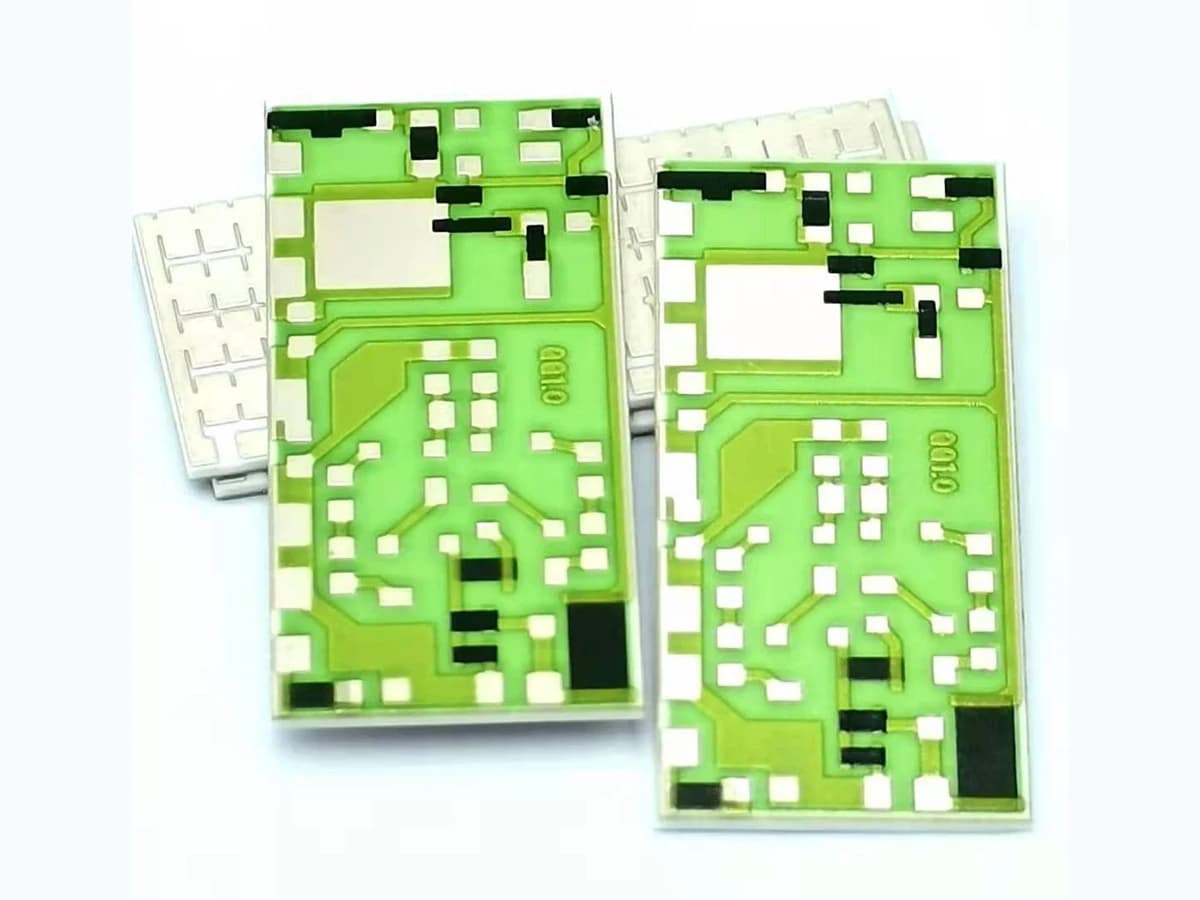
Overview
Low temperature coefficient of resistance is a system requirement, not a universal label for a resistor paste. TCR depends on the named material family, processed film, sheet-resistance range, substrate, conductor terminations, geometry, firing and refire history, trim, protection, test interval, and measurement method. Selection must also protect resistance range, power behavior, noise, stability, manufacturable geometry, and supply control instead of optimizing one typical TCR value in isolation.
Engineering review matrix
Each row links a design variable to evidence that can support a drawing or release decision.
| Variable | Control question | Verification route |
|---|---|---|
| TCR definition and interval | Specify reference temperature, temperature interval, equation or reporting convention, loading, stabilization, and whether limits apply to each element or a matched ratio. | Calculate from traceable resistance measurements at the defined temperatures and retain the raw values and method. |
| Resistance and sheet-resistance range | Match the target resistance and available geometry to a named processed resistor family without uncontrolled blending or extrapolation. | Review supplier data within its stated scope and confirm representative fired or cured samples in the intended resistance range. |
| Substrate and surface | Identify material grade, surface condition, thickness, thermal behavior, cleanliness, previous layers, and expansion relationship. | Inspect and record the controlled substrate condition and compare results only within the released substrate route. |
| Conductor termination system | Define conductor composition, resistor overlap, geometry, sequence, refires, joining or contact method, and possible interface contribution. | Use test structures or product measurements that include the real terminations and processing sequence. |
| Firing, curing, and refire history | Control the material-specific thermal profile, atmosphere, loading, layer order, number of later thermal cycles, and deviation handling. | Record the workpiece process history and correlate it with resistance and temperature-behavior data. |
| Geometry, load, and thermal field | Review length, width, aspect ratio, thickness variation, trim shape, terminal crowding, operating power, duty, and local heat removal. | Measure resistance and temperature behavior in representative geometry under controlled low-load and application-load conditions. |
| Trim and protection sequence | Define pre-trim target, cut topology, stopping method, post-trim settling, overglaze or overcoat, refire or cure, and exposed interfaces. | Compare pre-trim, post-trim, post-protection, and delayed values using the same measurement definition. |
| Stability and environment | Allocate allowed change for assembly heat, storage, humidity, media, bias, cycling, overload, aging, calibration, and service conditions. | Run the agreed exposure matrix on the released stack and report change without generalizing beyond the sample and conditions. |
Controlled model
TCR and processed-resistance screening model
Calculate temperature behavior only after fixing the reference temperature, interval, measurement loading, stabilization, heating direction, material stack, and processed geometry. Compare like-for-like material systems; a supplier coupon value from another sheet-resistance decade or stack is not a product result.
α_secant = [R(T₂) − R(T_ref)] / [R(T_ref) (T₂ − T_ref)] × 10⁶Average, or secant, temperature coefficient of resistance between a defined reference temperature and a second temperature.
- Units
- α_secant in ppm/K; R in Ω; T in °C or K for temperature differences
- Use boundary
- State T_ref, T₂, dwell, direction, excitation, and reporting convention. One secant slope can hide nonlinearity or hysteresis and must not be extended outside the tested interval.
R ≈ R_s (L / W)First estimate of a uniform rectangular printed resistor from processed sheet resistance and effective number of squares.
- Units
- R in Ω; R_s in Ω/□; L and W in the same length unit; L/W dimensionless
- Use boundary
- Valid only as a geometry screening relation. Termination overlap, current spreading, corners, thickness variation, firing movement, and trim geometry require correction and measured correlation.
Δq / q ≈ (α₂ − α₁) ΔTFirst-order ratio change for two elements at the same temperature, showing the role of differential TCR rather than absolute TCR alone.
- Units
- Δq/q dimensionless or ppm; α in ppm/K; ΔT in K
- Use boundary
- Use only for small changes with both elements at the same uniform temperature. Separate element temperatures, gradients, nonlinear response, loading, and long-term drift need their own terms.
- Absolute element TCR and differential TCR tracking are different requirements and need separate acceptance limits.
- Use low enough measurement loading to control self-heating, and report irreversible drift separately from reversible temperature response.
Failure controls
These are review prompts, not evidence that every risk applies or that every test is available.
- A
Selecting from a single typical TCR value while ignoring its sheet-resistance decade and test conditions
- B
Assuming a low initial TCR also guarantees low noise, low drift, power handling, or ratio stability
- C
Transferring supplier coupon data to a different substrate, termination, firing sequence, geometry, or protection layer
- D
Changing TCR or resistance through refiring, aggressive trimming, local self-heating, or termination interaction
- E
Reporting an average slope that hides nonlinearity, hysteresis, element mismatch, or a narrower valid interval
- F
Losing material identity or process traceability after qualification and invalidating the comparison
Low-TCR material selection workflow
The order makes assumptions and ownership visible before a result is promoted to a requirement.
- 01
Define temperature behavior
State the reference temperature, lower and upper limits, measurement points, ramp or dwell, operating load, allowed nonlinearity or hysteresis, and whether the requirement is absolute TCR, ratio tracking, or system calibration error.
- 02
Screen compatible material families
Compare named resistor systems at the required sheet-resistance decade together with the substrate, conductor termination, firing atmosphere, profile, refires, overglaze or overcoat, and supplier process conditions.
- 03
Translate data into the real geometry
Check effective squares, aspect ratio, terminations, current density, trim allowance, thermal gradients, neighboring heat sources, and available area. Typical test-coupon behavior is not automatically the product result.
- 04
Balance TCR against other risks
Review absolute tolerance, ratio tracking, voltage and power effects, noise, trim response, overload, humidity or media, long-term change, availability, lot control, and change notification before choosing a route.
- 05
Validate and freeze the stack
Build representative samples, record the complete process and measurement method, test across temperature and relevant load or environment, and release only the construction and conditions supported by the data.
Reference boundary
Public method sources
These sources support the engineering method and terminology used in this technical guide. They do not establish a ThickFilmPCB material list, capability limit, customer result, certification, or finished-product specification.
- 01IEC 60115-1:2020 — Fixed resistors, generic specification
Supports common fixed-resistor terminology and test-method framing for temperature and other influences only; it does not select a paste system or establish any ChipSimple TCR, tolerance, or reliability value.
- 02Heraeus — R8900 Series air-fired resistor system technical data sheet
Supports screening a named thick-film resistor family by sheet resistance, TCR, geometry, firing, termination, and stated test conditions only; its typical values cannot be transferred to another stack or represented as ChipSimple capability.
- 03NIST bibliographic record — Measurement, use, and interpretation of metallization TCR
Provides the authoritative title, authors, date, and journal citation for a TCR measurement and interpretation paper only. The full paper must be reviewed before relying on a specific method or equation; the bibliographic page does not endorse a material choice or provide a finished thick-film resistor or ChipSimple TCR claim.
Inputs for a practical review
Unknown values may be labelled unknown. The review should convert uncertainty into an explicit decision or validation task.
Send Drawings- 01
Target resistance or ratio, absolute tolerance, TCR or tracking requirement, temperature interval, and reporting method
- 02
Substrate material and grade, surface condition, dimensions, conductor system, layer stack, and assembly interfaces
- 03
Resistor geometry, available area, terminations, trim access, protection, and measurement nodes
- 04
Firing or curing route, later thermal cycles, assembly temperatures, atmosphere, and process restrictions
- 05
Voltage, current, power, duty, thermal environment, neighboring heat sources, and fault loads
- 06
Humidity, media, cleaning, vibration, cycling, storage, life, calibration, and stability expectations
- 07
Prototype quantity, material documentation, lot control, change notification, validation samples, and required data