
On this page
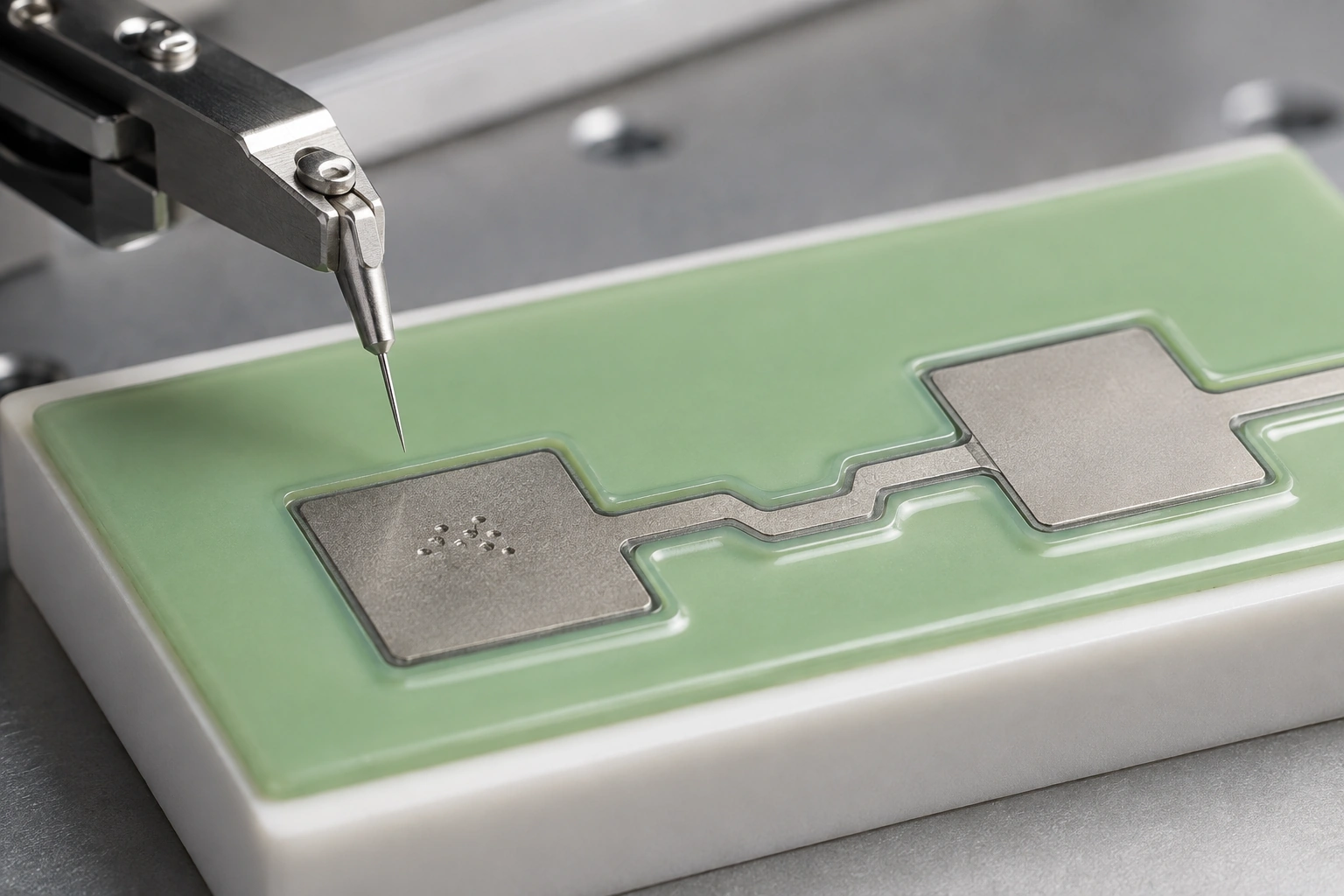
A nominal pad can contain the intended bond footprint and still be unusable when the capillary approaches at an angle, the substrate is displaced, or nearby overglaze and components obstruct the tool body. This calculation converts those mechanical envelopes into a conservative landing region. It is a layout screen, not a substitute for material compatibility, bond-process development or pull and shear evidence.
Key design decisions
- Separate the small bond deformation from the larger moving tool envelope.
- Project angular approach and height into lateral clearance at the obstruction plane.
- Reject a layout when the worst-case landing set is empty, even if its nominal drawing looks centered.
Define the geometry question before assigning a pad size
This page owns a specific pre-layout question: can every permitted bond center be reached while the bond footprint remains on the usable metal and the capillary remains clear of adjacent features? It does not select conductor chemistry, wire alloy, ultrasonic settings or acceptance force. Those decisions require a named material stack and representative bonding evaluation. The calculation starts only after the bond type, tool drawing and approach direction are identified.
Mark the finished pad boundary, not just its artwork. Exclude glass overglaze intrusion, dielectric bleed, probe marks, contaminated handling zones and any edge region prohibited by the bonding owner. Add die, wire, lid, fixture and previously bonded-wire keepouts at their relevant heights. A two-dimensional clearance drawn at the ceramic surface can miss interference higher on the tapered capillary.
Build three nested envelopes
First define the bond footprint envelope: the maximum plan-view region occupied by the accepted deformation, including its orientation tolerance. Second define the bond-center uncertainty from substrate location, vision alignment, bonder placement and datum transfer. Third define the tool envelope at every height where an obstacle may be encountered. Do not collapse the three into one undocumented margin because each responds to a different design change.
The usable center region is the finished pad eroded inward by the footprint envelope. The reachable center region is then that result reduced by positional uncertainty. Tool-access clearance is evaluated separately against neighboring obstacles. This order makes failure interpretable: enlarging a pad can recover landing area, while it cannot remove a tall die from the capillary path.
Calculate the remaining rectangular landing window
For an axis-aligned preliminary screen, subtract the maximum bond-footprint dimension and twice the directional placement allowance from the minimum finished pad dimension. A positive result is the range available to the programmed bond center. Repeat in both axes. The footprint dimension must include the permitted bond rotation or use its rotated bounding box; width alone is insufficient for an elongated wedge impression.
Assume a minimum finished pad of 0.80 by 0.65 millimeter, a footprint envelope of 0.32 by 0.18 millimeter, and placement allowances of 0.07 and 0.06 millimeter. The remaining center ranges are 0.34 millimeter in X and 0.35 millimeter in Y. These assumed values illustrate arithmetic only. A real release uses the measured pad, process-owner footprint and drawing-specific tolerance distributions.
Cx = Pxmin − Bx − 2Ex; Cy = Pymin − By − 2Ey
- Pxmin and Pymin are minimum usable finished-pad dimensions.
- Bx and By are maximum axis-aligned bond-footprint envelope dimensions.
- Ex and Ey are conservative bond-center placement allowances per side.
- Cx and Cy are the remaining permitted center ranges.
Centered rectangular screening model. Asymmetric pads, rotated footprints and nonrectangular exclusions require an explicit geometric overlay.
Project tool tilt into the obstacle plane
A tool tilted by angle theta shifts laterally as height increases. At an obstacle plane h above the bond surface, the centerline shift is h times tangent theta. Add the capillary radius at that height, runout and obstacle-position allowance to obtain a keepout from the programmed bond center. Use the manufacturer's actual tool profile; a constant-radius cylinder is only a screening approximation.
With an assumed obstacle plane 1.2 millimeters above the pad and a three-degree tilt toward the obstacle, centerline shift is about 0.063 millimeter. If the capillary radius there is 0.20 millimeter, runout allowance is 0.02 millimeter and obstacle-location allowance is 0.04 millimeter, the required center-to-obstacle distance becomes 0.323 millimeter. Reverse the tilt direction for the opposite-side check rather than applying one favorable sign everywhere.
Dreq(h) = rtool(h) + h tan(|θ|) + Erunout + Eobstacle
- h is height above the bond surface at the evaluated obstacle plane.
- θ is tool-axis tilt toward that obstacle.
- rtool(h) is the tool radius at height h.
- Erunout and Eobstacle are declared lateral allowances.
Rigid straight tool axis and one projected direction. Dynamic sweep, wire loop and machine-specific approach motion are checked separately.
Combine landing and access without double counting
Suppose the closest tall feature lies 0.50 millimeter from the minimum finished pad edge on the approach side. The preceding 0.323 millimeter tool requirement does not consume pad width directly; it constrains which bond-center positions are reachable relative to that feature. Overlay the allowed center rectangle with the feature keepout. If the overlap removes 0.10 millimeter from the 0.34 millimeter X range, 0.24 millimeter remains for programming and observed drift.
Do not add every tolerance arithmetically when the same datum error has already been included in both pad and obstacle positions. Construct a datum chain showing which errors are common and which are relative. A conservative sum is appropriate when correlation is unknown, but documenting the variables prevents accidental duplication and lets inspection target the dimensions that actually dominate clearance.
| Result | Geometry conclusion | Required follow-up |
|---|---|---|
| Cx or Cy is zero or negative | No guaranteed bond-center set remains | Change pad, footprint, tolerance or process concept |
| Landing set exists; tool set is empty | Footprint fits but capillary cannot approach | Move obstacle, change approach or review a compatible tool |
| Tool clears; loop crosses keepout | Immediate bond is reachable but wire path conflicts | Evaluate loop and second-bond sequence |
| Nominal access passes; result is tolerance-sensitive | Small datum change controls feasibility | Measure finished geometry and preserve capability evidence |
| Geometry passes; bond failure remains | Layout is not the limiting proof | Review surface, support, process and failure location |
Verify the envelope on representative finished circuits
Measure the fired pad and nearby glass boundary from the same datum used by assembly. Record the actual capillary identity, orientation, tool height and obstacle geometry. Program bonds at representative center and boundary positions rather than proving only one convenient nominal location. Retain images of footprints and clearance at the tightest locations, including the order in which adjacent wires are placed.
A successful dry approach is useful but incomplete. Bonding introduces force, energy, wire feed and deformation, and the substrate support can move the surface relative to the tool. Complete the appropriate electrical and mechanical evaluations for the named stack. Classify wire break, interface separation, pad lift, ceramic damage and access collision separately so a geometry correction is not credited for a material failure.
Use the failure signature to revise the correct envelope
A footprint clipped by the same pad edge across a panel points toward center allocation, pad registration or programmed offset. Scrubbing against overglaze points to an incorrect usable-metal boundary. A capillary witness mark on a die edge identifies tool-body interference even when the bond itself looks centered. Random footprint rotation suggests the process and tooling state should be reviewed before artwork is changed.
If the first bonds pass but later bonds become inaccessible, inspect sequence, existing wire loops and fixture orientation. If an edge location fails mechanically without geometric clipping, compare support beneath the pad and failure plane. Preserve these distinctions in the correction record; simply enlarging every pad can consume routing space without addressing the observed mechanism.
Release a coordinate-controlled bonding package
The drawing package should identify minimum usable pad boundaries, forbidden regions, bond-center windows, tool approach, obstacle heights, wire direction and datum ownership. Link the selected tool profile and process-owner footprint envelope to the revision. State which values are design allowances and which were measured on representative finished parts.
Reopen the calculation when wire type, tool, die height, overglaze opening, substrate location, fixture or bonding sequence changes. The useful output is not a universal minimum pad dimension. It is a traceable set of reachable bond centers for one declared assembly configuration, followed by evidence that the selected material and process form acceptable bonds.
Send the wire-bond landing and tool-access geometry
Provide the complete assembly envelope so landing area and capillary access can be reviewed against the finished ceramic circuit.
- Finished pad, overglaze, die, component and fixture drawings tied to common datums.
- Wire or ribbon, bond type, footprint envelope, capillary or wedge drawing and approach direction.
- Placement, registration, runout and obstacle tolerances with their measurement states.
- Bond sequence, loop envelope, support arrangement and any observed clipping, collision or failure locations.
The drawing-upload form loads as you reach this section.