
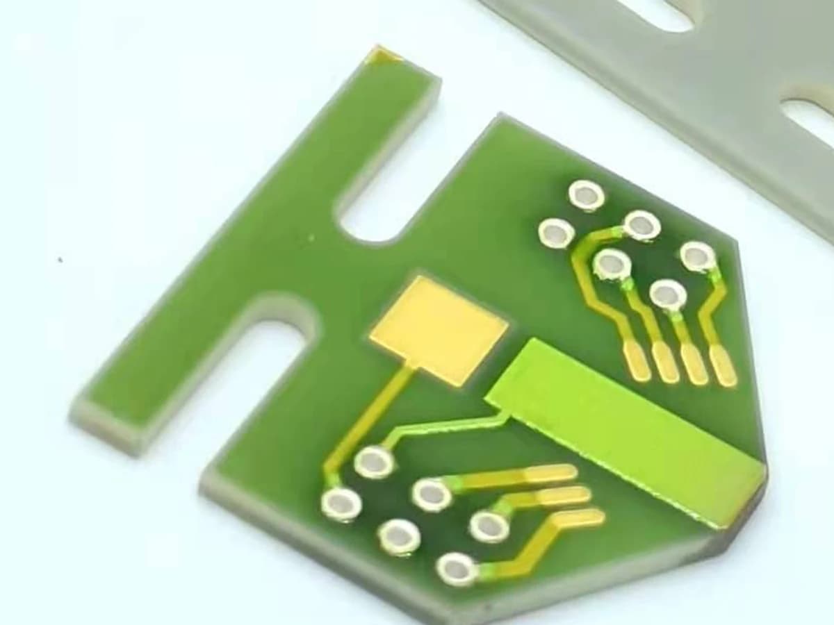
Overview
A via does not have a portable current rating. Its electrical resistance and temperature rise depend on the actual via construction, effective conductor cross-section, material state, length, terminations, current spreading, neighboring layers, duty cycle, heat extraction, ambient, and process variation. A first estimate can connect resistance and Joule loss to a thermal model, but current capacity is released only by measurement on the defined stack and production-intent interfaces.
Engineering review matrix
Each row links a design variable to evidence that can support a drawing or release decision.
| Variable | Control question | Verification route |
|---|---|---|
| Via construction and material state | Name the ceramic or substrate route, via formation method, conductor family, fill or wall structure, layer sequence, firing or curing history, and protection. | Use process records, cross-section or another approved construction check, and electrical correlation for the actual route. |
| Effective conductive geometry | Define via length, nominal and minimum opening, conductive area, void or discontinuity allowance, taper, pad overlap, neck-down, and datum. | Measure representative geometry with a method capable of resolving the current-carrying section and its interfaces. |
| Electrical resistance model | Use effective processed resistivity, path length, area, interfaces, temperature dependence, and probe locations; keep assumptions and units visible. | Compare calculated values with four-wire or otherwise suitable measurements on representative structures at controlled temperature. |
| Current waveform and sharing | Record continuous, pulse, surge, repetition, duty, polarity, source impedance, fault duration, and how current divides among parallel vias and planes. | Instrument the intended path and verify the actual waveform and sharing under nominal and worst credible conditions. |
| Thermal boundary | Define substrate thickness and properties, pad and plane geometry, adjacent heat sources, mounting, interface materials, heat sink, airflow or fluid, and ambient. | Correlate temperature mapping or embedded measurements with the production-intent assembly and load sequence. |
| Interface current crowding | Review conductor entry, pad overlap, corners, layer transitions, printed thickness, nearby isolation features, and local thermal gradients. | Inspect and measure at the via-to-pad transitions, not only at remote test points. |
| Process and lot variation | Allocate variation for printing or filling, registration, drying, firing or curing, shrinkage, refires, cleaning, defects, and inspection resolution. | Use samples across relevant panel positions and lots and retain the construction and measurement context. |
| Release and endurance criteria | Set allowable voltage drop, temperature, resistance change, continuity, isolation, physical condition, cycles, sample plan, and fault response for the project. | Run the agreed load, cycling, environment, and post-test inspection without converting a sample result into a universal rating. |
Controlled model
Construction-specific via electrothermal model
Choose the cross-section equation only after identifying whether the current path is a filled conductor, a wall coating, or another measured construction. Use effective processed properties and production-intent thermal boundaries; copper plated-through-hole examples are not ratings for fired or filled ceramic vias.
R_via = ρ_eff L / A_effFirst estimate of via-path resistance from effective processed resistivity, current-path length, and effective conductive cross-section.
- Units
- R_via in Ω; ρ_eff in Ω·m; L in m; A_eff in m²
- Use boundary
- Applicable only when a reasonably uniform effective path is justified. Add pad, neck-down, interface, contact, void, taper, and temperature-dependent terms where material.
A_filled = π d_eff² / 4Idealized conductive area for a fully filled circular path with an effective diameter.
- Units
- A_filled in m²; d_eff in m
- Use boundary
- Do not use nominal hole diameter unless fill, voids, taper, shrinkage, interfaces, and minimum effective diameter are verified for the actual process.
A_wall = π (D_o² − D_i²) / 4 ≈ π d tAnnular cross-section for a wall-metallized barrel; the approximation applies when wall thickness is small relative to diameter.
- Units
- A_wall in m²; D_o, D_i, d, and t in m
- Use boundary
- Use only for a verified continuous wall construction. It is not applicable to a filled paste via, surface ring, interrupted coverage, or unknown internal geometry.
P_loss = I_rms² R_viaElectrical loss in the via path for a periodic or steady current represented by its RMS value.
- Units
- P_loss in W; I_rms in A; R_via in Ω
- Use boundary
- RMS loss does not by itself qualify surge, pulse-energy, peak-current, electromigration, interface, or transient thermo-mechanical limits.
ΔT ≈ P_loss θ_thFirst-pass steady-state temperature rise for a defined lumped thermal path.
- Units
- ΔT in K; P_loss in W; θ_th in K/W
- Use boundary
- Use only as a correlated steady-state model. Local current crowding, thermal spreading, neighboring heat sources, transient duty, mounting, airflow, and fluid boundaries require detailed analysis or measurement.
Decision comparison
| Decision | Route A | Route B | Verification |
|---|---|---|---|
| Current-carrying cross-section | A filled-via model uses a verified minimum effective filled area and processed conductor state. | A wall-metallized model uses verified continuous coverage, wall thickness, finished diameter, and interface geometry. | Use a released section drawing plus microsection or another approved construction check; a surface ring is insufficient. |
| Qualification evidence | A calculation estimates resistance and loss from measured, construction-specific inputs. | A production-intent test measures four-wire resistance or voltage drop, temperature, sharing, cycling, and physical condition. | Correlate both routes and release only the named stack, geometry, waveform, assembly, environment, sampling, and acceptance limits. |
- Use processed effective resistivity or measured resistance correlation rather than substituting bulk-metal resistivity.
- Parallel vias require measured or bounded sharing; equal current division is not an automatic assumption.
Via electrothermal review
The order makes assumptions and ownership visible before a result is promoted to a requirement.
- 01
Identify the via construction
Define substrate, layer sequence, via length, opening, fill or wall geometry, conductor material, refires, top and bottom pads, parallel paths, protection, and whether the proposed construction has process evidence.
- 02
Build the electrical estimate
Estimate resistance from effective resistivity, current-path length, and effective conductive area where that model is appropriate. Add pad, neck-down, interface, contact, and temperature-dependent contributions instead of treating the via as an ideal cylinder.
- 03
Map loss into the thermal stack
Use current and estimated resistance to locate Joule loss, then model conduction into the substrate, pads, adjacent metal, assembly, and ambient. Include current crowding and local heat sources near the via.
- 04
Apply variation and derating
Evaluate minimum effective conductor area, material and processing variation, via-to-via sharing, ambient extremes, continuous and transient duty, repeated cycling, and measurement uncertainty against explicit acceptance limits.
- 05
Validate representative structures
Measure resistance or voltage drop and temperature on production-intent vias and interfaces under the required load profile, then inspect for opens, cracks, delamination, migration, drift, or adjacent dielectric damage.
Failure controls
These are review prompts, not evidence that every risk applies or that every test is available.
- A
Publishing a universal ampacity from nominal diameter while ignoring effective fill, material state, and interfaces
- B
Using bulk-metal resistivity for a processed thick film conductor without measured correlation
- C
Missing current crowding and heat concentration at pad transitions, neck-downs, or nearby thermal sources
- D
Assuming identical current sharing among parallel vias despite path, resistance, temperature, or defect variation
- E
Validating a coupon with a different substrate, pad plane, mounting, cooling, duty, or ambient from the product
- F
Accepting room-temperature continuity while overlooking cycling, drift, cracking, isolation damage, or fault behavior
Reference boundary
Public method sources
These sources support the engineering method and terminology used in this technical guide. They do not establish a ThickFilmPCB material list, capability limit, customer result, certification, or finished-product specification.
- 01IPC-2152 — official table of contents and scope for printed-board conductor sizing
The public document supports the stated scope relationship among current, conductor size, and temperature and identifies via guidance inside a copper printed-board standard. Detailed use requires review of the licensed standard; it is not a current rating for a fired thick-film via or a ChipSimple capability.
- 02Sierra Circuits — High-Speed PCB Design Guide (hosted by NASA SSRI Knowledge Base)
Provides an illustrative flatten-the-barrel approximation for a plated copper printed-board via. Sierra Circuits authored the guide; NASA SSRI hosts it as a third-party resource. The construction and assumptions differ from printed or filled ceramic vias, so no numerical limit is transferable.
- 03Heraeus — IP9217 multilayer dielectric technical data sheet
Supports considering via opening, dielectric thickness, screen, firing, and compatible material stack for one named multilayer dielectric only; it supplies no via-current rating and no ChipSimple process capability.
- 04DuPont — 7740 thick-film silver conductor technical data sheet
Supports the method boundary that conductor resistance, thickness, geometry, substrate, and processing are coupled in high-current design; reported values are supplier-specific typical data and do not rate a via or establish ChipSimple capability.
Inputs for a practical review
Unknown values may be labelled unknown. The review should convert uncertainty into an explicit decision or validation task.
Send Drawings- 01
Layer stack and section drawing with substrate, via construction, length, opening, pads, planes, neck-downs, and protection
- 02
Conductor material-system information, processing sequence, refires or cures, and available construction evidence
- 03
Continuous, pulse, surge, repetition, duty, source, return path, parallel-via sharing, and fault-current conditions
- 04
Allowed voltage drop, temperature, resistance change, continuity, isolation, endurance, and post-test criteria
- 05
Assembly heat path including substrate, nearby losses, mounting, interface, heat sink, airflow or fluid, and ambient
- 06
Probe points, fixture, instrument method, thermal measurement locations, sampling, traceability, and report format
- 07
Prototype structures, production context, cycling or environment plan, failure analysis, and change-control needs