
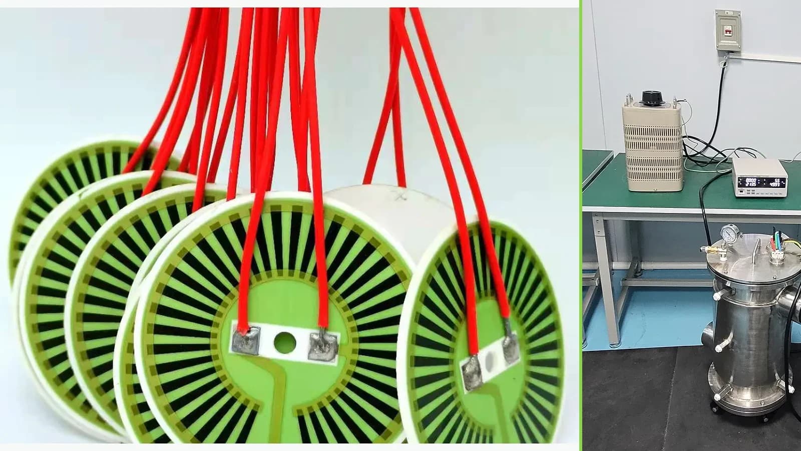
Overview
A multi-zone heater is a coupled thermal-control system, not several independent resistance calculations placed on one substrate. Every zone shares heat through the substrate, heated body, interfaces, mounting hardware, insulation, fluid, radiation, and ambient. Changing power in one zone therefore changes neighboring temperatures and the controller's apparent load. The design must start with the required temperature field and dynamic states, then allocate sensors, electrical feeds, resistance targets, trace geometry, power electronics, control authority, and fault containment. Edge zones often face different losses from center zones; terminals and mounting features disturb both electrical and thermal fields; production tolerances can rotate the balance; and a sensor can report a controlled point while an unmeasured area overheats. This guide presents a bounded thermal-network and zone-interaction method. It does not claim a ThickFilmPCB zone count, power density, warm-up time, temperature, voltage, uniformity, isolation, controller, or life capability. Those values depend on the actual drawing, named material stack, heat-transfer boundary, control system, protection, and production-intent validation.
Failure controls
These are review prompts, not evidence that every risk applies or that every test is available.
- A
Assuming separate electrical channels are thermally independent and ignoring off-diagonal coupling between zones
- B
Tuning equal-area or equal-resistance zones in free air while the production load, contact, edges, fasteners, flow, and insulation are different
- C
Controlling a convenient sensor location while an unmeasured turn, terminal, edge, void, or low-contact region becomes hotter
- D
Allocating all power at nominal steady state and leaving no upward, downward, warm-up, disturbance, or supply-tolerance control authority
- E
Allowing one controller to conceal resistance, contact, sensor, or assembly variation without diagnostic and acceptance limits
- F
Failing to contain a stuck output, shorted zone, open sensor, connector fault, loss of load, dry run, or unexpected coupling
Engineering review matrix
Each row links a design variable to evidence that can support a drawing or release decision.
| Variable | Control question | Verification route |
|---|---|---|
| Required spatial temperature field | Define points, regions, gradient direction, uniformity calculation, setpoints, tolerances, transient states, and hard limits. | Use an independent, position-registered temperature map and compare every state with the specified metric and sensor readings. |
| Zone geometry and coupling | Set zone boundaries, active areas, gaps, overlap of thermal influence, edge compensation, and separation from mounting and terminals. | Identify the measured influence matrix from zone-step tests and correlate it with the model over relevant conditions. |
| Electrical resistance and drive | Specify each zone's cold and hot resistance model, supply tolerance, current, power, wiring drop, switching method, resolution, and channel limits. | Record four-wire resistance where appropriate, voltage, current, command, and temperature during startup, steady, disturbance, and fault tests. |
| Trace current and heat density | Review widths, spacing, turns, necks, crossovers, terminals, conductor-resistor transitions, trim features, inactive margins, and local heat spreading. | Inspect production geometry and compare modeled or measured hot spots with electrical and thermal maps. |
| Thermal interfaces and load | Define contact area, flatness, pressure, interface material, heated mass, flow, phase, insulation, heat sink, edge losses, and installation tolerance. | Test nominal and bounded interface conditions in the real mounting orientation and retain assembly measurements. |
| Sensors and observability | Define sensor type, location, attachment, tolerance, drift, response, self-heating, wiring, calibration, redundancy, and relation to maximum surface temperature. | Cross-check controller sensors against independent references and intentionally evaluate sensor displacement and failure. |
| Control dynamics and authority | Set sample period, filters, controller gains or logic, output limits, ramp, sequencing, cross-coupling treatment, overshoot, settling, and upward and downward margin. | Run setpoint, load, ambient, supply, and flow disturbances with logged commands and temperatures; assess stability and saturation. |
| Fault containment and protection | Define stuck-on, open or short zone, open or biased sensor, connector fault, loss of load or flow, dry run, ground fault, and controller reset behavior. | Use a reviewed fault-injection plan and independent protective limits without relying only on the normal control loop. |
Controlled model
Coupled electrical, thermal, and control-zone model
Represent each zone as an electrical heat source connected through a thermal network to every relevant node. Use a coupling matrix or calibrated finite-element model when lateral heat flow is material. The equations establish bookkeeping; measured boundary conditions and validation determine acceptance.
Pᵢ = VᵢIᵢ = Iᵢ²Rᵢ = Vᵢ²/RᵢElectrical power applied to zone i under the stated supply and control condition.
- Units
- Pᵢ in W; Vᵢ in V; Iᵢ in A; Rᵢ in Ω
- Use boundary
- Use temperature-dependent resistance and real drive topology. Electrical input is not equal to useful heat delivered at a target surface.
Cᵢ dTᵢ/dt = Pᵢ − Σⱼ Gᵢⱼ(Tᵢ − Tⱼ) − Q_loss,iLumped transient energy balance for a thermal node with storage, inter-node conduction, and external losses.
- Units
- C in J/K; T in K or °C differences; G in W/K; P and Q in W; t in s
- Use boundary
- A simplified network requires defined nodes, approximately lumped temperatures, and identified losses. Radiation, flow, contacts, temperature-dependent properties, and phase changes may require a nonlinear distributed model.
ΔT = Θ PLinearized steady-state relation between the vector of zone powers and temperature rises through a thermal influence matrix.
- Units
- ΔT in K; Θ in K/W; P in W
- Use boundary
- Valid only near the calibrated operating boundary where properties, contacts, convection, and radiation can be linearized. Off-diagonal terms represent cross-coupling and must not be ignored.
mᵢ = (Pᵢ,max − Pᵢ,steady)/Pᵢ,maxA simple positive control-authority margin for increasing heat in zone i from its nominal steady state.
- Units
- Dimensionless
- Use boundary
- This margin says nothing about cooldown authority, response time, power-electronics limits, sensor failure, overshoot, or safety. Define both upward and downward margins for each state.
Decision comparison
| Decision | Route A | Route B | Verification |
|---|---|---|---|
| Independent electrical zones versus thermally independent zones | Separate terminals or drive channels permit independent electrical commands and diagnostics. | Thermal independence depends on lateral conduction, load contact, insulation, flow, radiation, and geometry; zones on one body remain coupled even with separate wiring. | Apply a small controlled power change to one zone and measure the time-resolved response at every sensor and mapped surface location. |
| One sensor per zone versus state estimation | A dedicated sensor can simplify local feedback but still measures only its placement, attachment, dynamics, and wiring path. | A model-based or multi-sensor estimate may better represent an extended field but adds model uncertainty, observability, calibration, and software validation obligations. | Compare controller observations with independent mapped temperatures through nominal, transient, tolerance, and fault cases. |
| Uniform trace density versus loss-compensated zoning | Uniform geometry is simpler but may underheat edges or overheat centers when heat losses and load contacts are nonuniform. | Locally adjusted resistance or power can compensate a known boundary, but becomes fragile if the assembly, flow, contact, or sensor position changes. | Validate the production-intent mounting, load, ambient, flow, insulation, and control sequence rather than tuning in free air. |
- A controller can hide manufacturing or assembly variation during normal operation; retain per-zone resistance, current, command, sensor, and map data for diagnostics.
- Safety limits should be independent enough to address stuck outputs, open sensors, shorted zones, loss of load, dry operation, changed flow, and unexpected thermal coupling.
Multi-zone heater design sequence
The order makes assumptions and ownership visible before a result is promoted to a requirement.
- 01
Specify the temperature field
Define controlled points, mapped regions, gradients, uniformity metric, heat-delivery face, warm-up, steady state, cycling, standby, disturbances, ambient, load variation, cooldown, and fault limits. Separate a sensor setpoint from allowable temperature everywhere else.
- 02
Map the assembly heat paths
Draw every layer and contact, interface material, clamp, fastener, edge, terminal, insulation, heat sink, heated mass, fluid or airflow boundary, radiation surface, and sensor attachment. Assign uncertainty instead of treating unknown contacts as perfect.
- 03
Partition functional zones
Place zone boundaries according to loss patterns, control objectives, sensor observability, electrical routing, trace manufacturability, mounting interruptions, terminals, and failure containment. Avoid creating a narrow corrective zone that cannot spread heat safely.
- 04
Co-design electrical architecture
Allocate supply range, zone resistance, current, nominal and peak power, trace width and spacing, turns, transitions, conductor feeds, connector pins, switching devices, isolation, grounding, fusing, and diagnostics. Include temperature coefficient and production tolerance.
- 05
Design sensing and control
Choose sensor types, locations, attachment, response, wiring, calibration, sampling, filtering, controller structure, output limits, anti-windup, startup, sequencing, setpoint transitions, and independent protection. Demonstrate that unmeasured hot regions remain bounded.
- 06
Correlate and validate
Use production-intent prototypes to identify zone coupling and time constants, correlate the model, map temperatures and electrical states, tune control, test tolerance and disturbances, and exercise credible open, short, sensor, drive, flow, contact, and dry-run faults.
- 07
Freeze the released system
Link heater drawing, material stack, assembly, interface pressure, sensors, controller hardware and software, limits, calibration, inspection, end-of-line test, validation record, and change-control triggers. A heater-only substitution cannot remain qualified when its boundary changes.
Reference boundary
Public method sources
These sources support the engineering method and terminology used in this technical guide. They do not establish a ThickFilmPCB material list, capability limit, customer result, certification, or finished-product specification.
- 01NASA — A numerical model including PID control of a multizone crystal growth furnace
Supports the general method of coupling a multidimensional thermal model with independently controlled heater zones to establish target temperature profiles; it is a furnace study, not a thick-film heater design value or company capability.
- 02NASA — Thermal Model, multi-zone heater power and gradient study
Supports modeling zone power, interfaces, control margin, and measured correlation in a coupled thermal system; the apparatus and numerical results are not transferable to a printed heater.
- 03NASA — Thermal Network Modelling Handbook
Supports thermal-network terminology, energy balances, node definition, and model-validation discipline only; it does not prescribe a heater stack, power density, temperature, or controller.
Inputs for a practical review
Unknown values may be labelled unknown. The review should convert uncertainty into an explicit decision or validation task.
Send Drawings- 01
Heated-assembly drawing with target face, required temperature or heat-flux map, controlled points, gradients, uniformity metric, and hard limits
- 02
Warm-up, steady, cycling, standby, cooldown, setpoint transitions, ambient, load, flow, contact, and credible disturbance profiles
- 03
Supply range, channel count, drive topology, target zone resistances or power allocation, current limits, wiring, connector, ground, and isolation
- 04
Substrate and printed stack, outline, thickness, active and inactive areas, holes, clamps, fasteners, interfaces, insulation, and heat-sink details
- 05
Sensor types, locations, attachment, tolerances, calibration, response, redundancy, controller hardware and software, communications, and logging
- 06
Normal protection and independent safety requirements for open, short, stuck-on, sensor, flow, load, ground, connector, and reset faults
- 07
Prototype quantity, mapping method, model and correlation deliverables, tolerance matrix, validation ownership, acceptance tests, and change control