
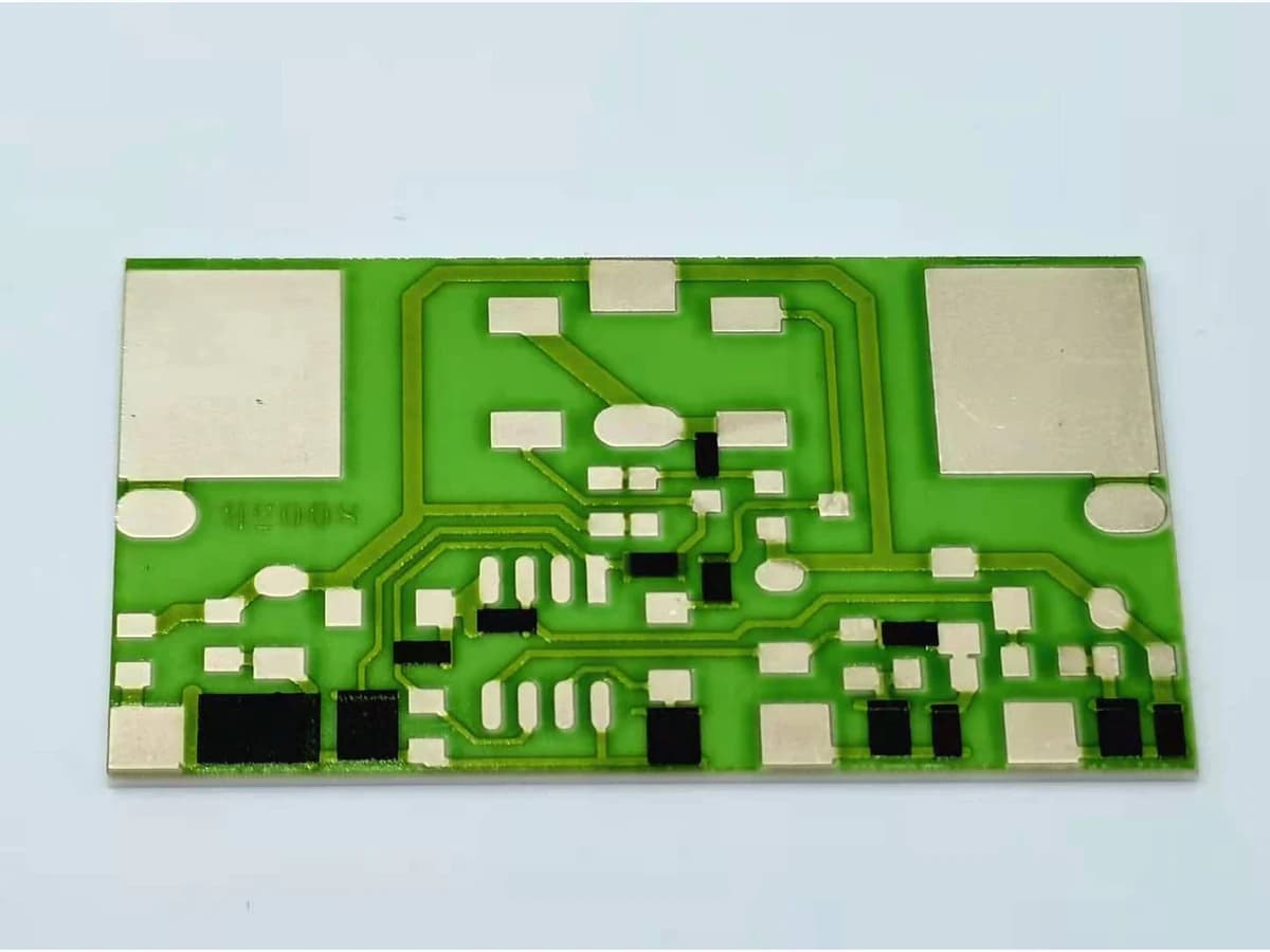
Overview
A finished-resistance tolerance is a specification limit, not measurement uncertainty and not a single printing limit. The allowable product error can be allocated across material and process variation, effective geometry, terminations, laser trimming, temperature, self-heating, environmental exposure, and change over time, while measurement uncertainty is evaluated and reported separately. A useful budget defines the measurand and reference condition first, separates bounded, correlated, and independent contributors, applies an explicit acceptance decision rule, and reserves margin for validation rather than assigning every error to final trim.
Engineering review matrix
Each row links a design variable to evidence that can support a drawing or release decision.
| Variable | Control question | Verification route |
|---|---|---|
| Nominal value and reference condition | Define the resistance target, measurement nodes, reference temperature, excitation, stabilization, and allowed total error. | Use one controlled test definition on drawings, fixtures, data sheets, and release records. |
| Material and processed sheet resistance | Tie the resistor family and target sheet-resistance range to its substrate, conductor terminations, firing sequence, refires, and processed film state. | Measure representative witness or product geometries by lot and process condition; do not substitute a generic supplier typical value. |
| Effective resistor geometry | Model length, width, thickness variation, termination overlap, current spreading, corners, neighboring layers, and printing or firing movement. | Inspect critical geometry and correlate measured resistance with the released artwork and processed dimensions. |
| As-fired distribution | Set an upstream distribution or bounded window that leaves sufficient trim range and avoids relying on excessive correction. | Review actual pre-trim data by cavity, panel position, lot, and relevant process variables. |
| Trim and post-trim change | Define trim topology, target, stopping rule, measurement condition, remaining current path, protection sequence, and allowed settling or drift. | Compare immediate and delayed post-trim data and inspect the cut and local current path under the agreed criteria. |
| Measurement uncertainty | Include instrument, fixture, leads or contacts, probe location, self-heating, temperature, repeatability, resolution, and calibration context. | Define the measurand and decision rule, confirm calibration and traceability, evaluate Type A and Type B inputs including fixture, contact, self-heating, and temperature effects, and record combined and expanded uncertainty separately from product variation. |
| Temperature and load effect | Account for TCR over the defined temperature range, local self-heating, duty, thermal gradients, and the resistance state used by the system. | Measure resistance or function at controlled temperatures and loads in the representative thermal assembly. |
| Environmental and long-term change | Identify humidity, media, bias, cycling, assembly heat, storage, protection, and aging contributors that belong inside the released life or calibration budget. | Use pre/post data from the agreed exposure and duration, without extending the result beyond the tested construction and conditions. |
Controlled model
Product-error and measurement-uncertainty model
Keep the product specification, the predicted product-error budget, and the measurement-uncertainty budget as separate records. Normalize contributors to one fractional unit before combining them, state correlation assumptions, and define the decision rule used at the tolerance boundary.
|ΔR / R|_WC ≤ Σ |e_i|Conservative worst-case combination of bounded fractional product-error contributors that may align.
- Units
- Dimensionless; normally reported consistently as % or ppm
- Use boundary
- Use for explicitly bounded product contributors. It is not a statistical confidence statement and it is not the measurement-uncertainty calculation.
u_c²(y) = Σ (c_i u_i)² + 2 Σ_{i<j} c_i c_j u_ijLaw of propagation for combined standard measurement uncertainty, including sensitivity coefficients and covariance terms.
- Units
- Same unit as the measurand y after propagation; resistance in Ω or normalized fractional resistance in % or ppm
- Use boundary
- Use only after defining the measurand, input estimates, standard uncertainties, sensitivity coefficients, and covariance. It reduces to root-sum-square only when covariance terms are justified as zero.
U = k u_cExpanded measurement uncertainty derived from combined standard uncertainty and a stated coverage factor.
- Units
- Same unit as the measurand or normalized error
- Use boundary
- Report the chosen k and coverage basis. Expanded uncertainty is not a product tolerance and does not by itself define pass or fail.
- Do not apply root-sum-square directly to supplier tolerance bands or bounded errors without a justified statistical model.
- Calibration, correction, and guard banding must remain visible rather than being absorbed into an unexplained product margin.
Tolerance-budget workflow
The order makes assumptions and ownership visible before a result is promoted to a requirement.
- 01
Define the measurand
State the nominal resistance, terminals or probe points, reference temperature, test current or voltage, stabilization time, direction if relevant, and whether the requirement applies to an element, network, curve, or assembled function.
- 02
List contributors by lifecycle stage
Separate material and firing variation, printed geometry, terminations, trim, protection and refire, measurement uncertainty, assembly, operating temperature and load, environment, and time-dependent change.
- 03
Choose a combination rule
Use worst-case addition for bounded product contributors that can align. Build measurement uncertainty separately with sensitivity coefficients and covariance. Use a statistical product estimate or root-sum-square form only when distributions, centering, correlation or independence, sample basis, and required confidence are justified and recorded.
- 04
Allocate margin and control points
Assign each contributor to a drawing rule, process control, trim window, measurement system, application boundary, or validation task. Keep reserve margin visible for unmodelled interaction and future drift.
- 05
Close the budget with evidence
Compare predictions with as-fired, post-trim, post-protection, assembled, environmental, and aged data under the defined method. Reopen the budget when material, geometry, process, test, or application conditions change.
Failure controls
These are review prompts, not evidence that every risk applies or that every test is available.
- A
Using a datasheet tolerance as the finished-circuit tolerance without the named geometry, stack, and process
- B
Combining correlated contributors by root-sum-square and understating a possible aligned worst case
- C
Treating laser trimming as compensation for an uncontrolled as-fired distribution or unsuitable geometry
- D
Mixing measurement-system variation with product variation and tightening the wrong control
- E
Specifying resistance at one temperature while the system uses a self-heated or different temperature state
- F
Consuming all tolerance at initial release and leaving no allowance for assembly, environment, calibration, or aging
Reference boundary
Public method sources
These sources support the engineering method and terminology used in this technical guide. They do not establish a ThickFilmPCB material list, capability limit, customer result, certification, or finished-product specification.
- 01IEC 60115-1:2020 — Fixed resistors, generic specification
Supports standard resistor terminology, inspection procedures, and test-method framing only; the licensed standard and project specification must define applicable requirements, and the reference does not prove ChipSimple tolerance performance.
- 02NIST Technical Note 1297 — Evaluating and expressing measurement uncertainty
Supports identifying, combining, and reporting measurement-uncertainty components only; it supplies no resistor capability value and does not justify statistical independence or a chosen coverage rule without project evidence.
- 03Heraeus — R8900 Series air-fired resistor system technical data sheet
Supports the method boundary that resistor properties depend on the named paste, sheet-resistance range, geometry, terminations, firing, and test conditions; supplier typical data apply only to that system and are not ChipSimple capabilities.
Inputs for a practical review
Unknown values may be labelled unknown. The review should convert uncertainty into an explicit decision or validation task.
Send Drawings- 01
Nominal resistance, total tolerance, measurement nodes, reference temperature, excitation, and stabilization method
- 02
Resistor function, schematic, artwork, substrate, conductor terminations, protection, and assembly stack
- 03
Operating temperature range, load, duty, self-heating boundary, thermal interface, and fault conditions
- 04
Required TCR, ratio or curve behavior, calibration strategy, and system error allocation
- 05
Firing or curing sequence, refires, trim access and method, post-trim protection, and later assembly heat
- 06
Measurement fixture, instrument context, sampling, data format, traceability, and acceptance rule
- 07
Environmental, endurance, storage, life, drift, prototype, and change-control requirements