
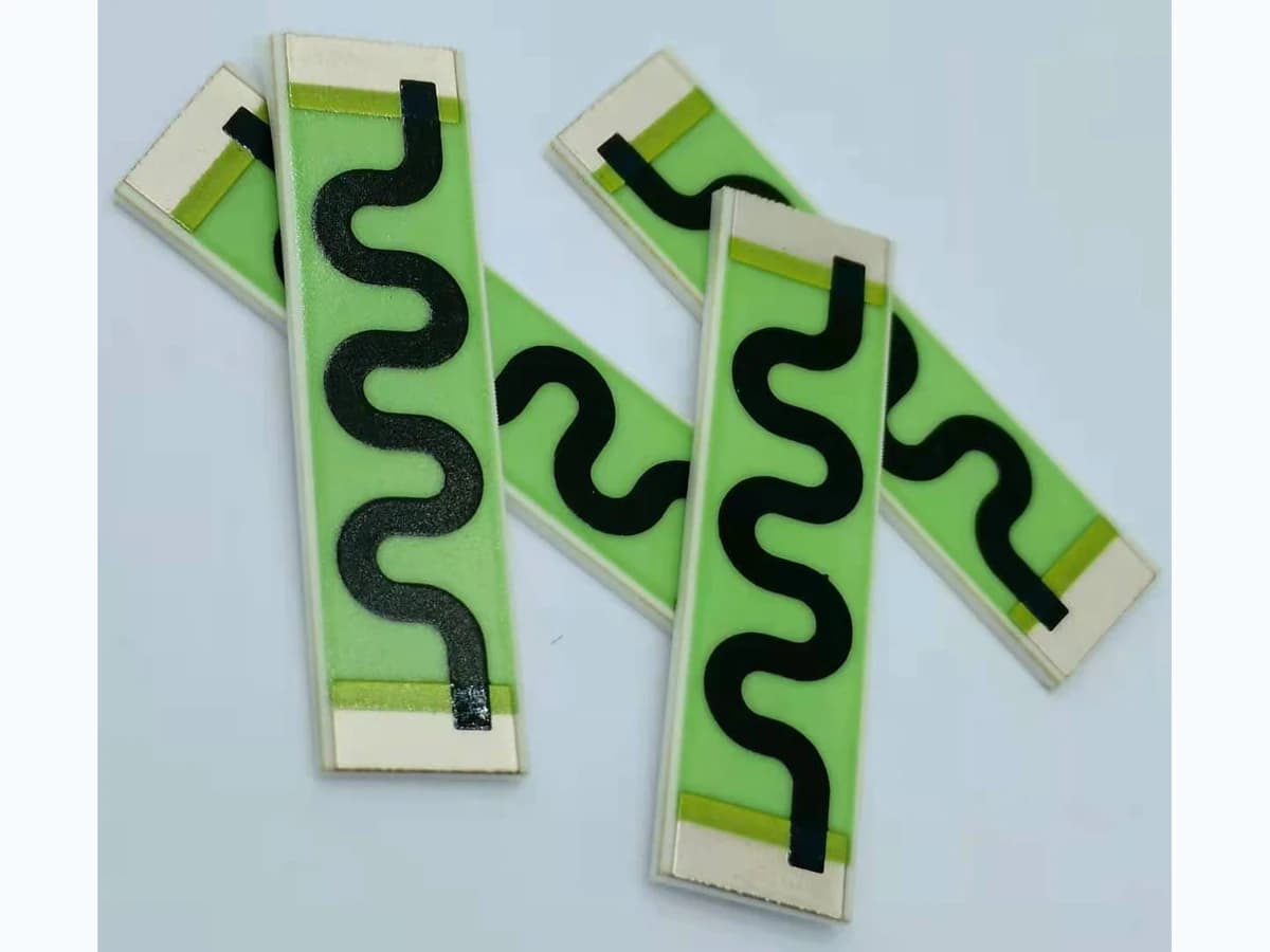
Overview
Voltage coefficient of resistance describes reversible resistance change associated with applied voltage under defined conditions, separate from temperature coefficient and long-term drift. In a printed thick-film resistor, material system, resistance decade, geometry, film profile, termination spacing, electric-field distribution, protective layers, substrate surface, humidity, measurement timing, and self-heating can all influence the observed result. A low-voltage room-temperature resistance cannot establish behavior at the application voltage, and a measured change cannot be assigned to VCR until temperature and instrument effects are controlled. Design must therefore manage field and power together and validate the exact element in its assembled boundary.
Engineering review matrix
Each row links a design variable to evidence that can support a drawing or release decision.
| Variable | Control question | Verification route |
|---|---|---|
| Voltage definition | Set node-to-node voltage, polarity, waveform, ramp, dwell, duty, transients, source impedance, current limit, and reference measurement level. | Capture actual element voltages and current with calibrated instruments through the stated sequence. |
| Resistor material | Name series, resistance decade, lot, substrate, conductor, print, firing, refires, trim, protection, and supplier test method. | Retain material/process identity and compare representative product geometry rather than transferring coupon typicals. |
| Geometry and field | Define effective length, width, thickness observation, corners, terminations, trim cuts, spacing, edges, neighboring potentials, and contamination assumptions. | Inspect critical fired features and correlate local geometry with voltage-dependent response and failures. |
| Thermal coupling | Allocate electrical power, self-heating, TCR, substrate, mounting, ambient, airflow, neighboring heat, sensor placement, and stabilization time. | Monitor temperature or justified proxy and repeat low-level resistance readings to separate thermal effects. |
| Leakage and insulation | Define substrate surface, dielectric/protection, humidity, residues, creepage, clearance, guarding, ground, accessible metal, and fault state. | Measure relevant leakage and apply project-selected insulation methods independently from the VCR calculation. |
| Measurement convention | State VCR equation, sign, units, voltage interval, timing, fixture, leads, guarding, instrument range, contact, averaging, and uncertainty. | Use reference artifacts or method checks and report raw readings plus calculation, temperature, and uncertainty. |
| Stability and changes | Set reversible recovery, permanent shift, humidity/bias, cycling, aging, acceptance, sampling, substitutions, drawing, and process change triggers. | Compare pre-bias, in-bias, recovered, and post-exposure data on configuration-linked samples. |
Controlled model
Voltage-coefficient and coupled thermal-error model
Define polarity, waveform, measurement level, dwell, temperature, and resistance reference. VCR conventions vary, so state the exact calculation rather than quoting a number without units or interval. Separate reversible voltage response from I-squared-R self-heating, leakage, contact effects, dielectric absorption, and irreversible electrical stress.
VCR = [(R(V₂) − R(V₁))/R(V₁)] / (V₂ − V₁)One explicit interval definition of fractional resistance change per applied-voltage change.
- Units
- 1/V, often expressed as ppm/V
- Use boundary
- The polarity, voltage interval, dwell, waveform, temperature, measurement timing, loading, and sign convention must be stated; do not mix with a supplier's different method.
E_avg ≈ V/L_effAverage longitudinal electric-field screen across an effective resistive length.
- Units
- V/m or V/mm
- Use boundary
- Local field can be higher at terminations, corners, trim cuts, thickness changes, surface defects, or contamination. This is not a dielectric-withstand equation.
ΔR/R ≈ VCR·ΔV + α·ΔTFirst-order separation of voltage-related and temperature-related resistance change.
- Units
- Dimensionless
- Use boundary
- Only a local linear screen. VCR and TCR may be nonlinear and coupled; power, time, humidity, hysteresis, drift, and measurement uncertainty need independent treatment.
Decision comparison
| Decision | Route A | Route B | Verification |
|---|---|---|---|
| Longer path versus higher sheet-resistance decade | Increasing effective length can lower average field for the same voltage but consumes area and may create narrow or thermally uneven geometry. | A higher resistance-decade material can shorten geometry but may exhibit different VCR, TCR, noise, stability, and process behavior. | Compare named material and geometry candidates at equal resistance, voltage interval, temperature control, protection, and measurement method. |
| Single element versus series distribution | One printed body simplifies nodes but concentrates voltage and makes its local geometry and terminations critical. | Series elements distribute voltage but add conductor transitions, tolerances, matching, spacing, nodes, leakage paths, and assembly complexity. | Map node voltages and measure element and network response under nominal and fault conditions with local temperature observation. |
- VCR is not dielectric breakdown voltage and does not replace creepage, clearance, insulation, or fault analysis.
- The resistance reading instrument can alter voltage and self-heating; its source, guarding, timing, and uncertainty belong in the method.
Voltage-coefficient design workflow
The order makes assumptions and ownership visible before a result is promoted to a requirement.
- 01
Define voltage states and error budget
Specify element and network values, node potentials, polarity, DC or waveform, startup, transients, dwell, duty, source/load, reference measurement level, temperature, humidity, calibration, and allowed reversible and irreversible resistance change.
- 02
Select material and geometry candidates
Review named resistor series, sheet resistance, controlled supplier VCR method, TCR, noise, stability, compatible conductor and protection, fired length/width, termination spacing, trim path, edges, and available area. Keep typical supplier data conditional.
- 03
Map field, power, and insulation
Estimate average field and local concentrations at terminations, corners, trim cuts, thickness variation, particles, protection openings, and surface paths. Calculate power and temperature rise separately; include creepage, clearance, dielectric layers, ground, accessible metal, and contamination.
- 04
Design a discriminating measurement
Use stated voltage steps or polarity sequence, dwell, current limit, guarding, fixture, contact method, temperature monitoring, stabilization, humidity, low-level references, repeat readings, and uncertainty. Prevent self-heating or leakage from being mislabeled as VCR.
- 05
Validate the real element and network
Characterize production-intent geometry through nominal and tolerance voltage, temperature, mounting, protection, humidity, cycling, and time. Compare individual elements and the loaded circuit so voltage distribution and ratio effects remain visible.
- 06
Issue bounded design rules
Tie any VCR interval, derating, geometry, series distribution, measurement, and acceptance rule to the named material, process, stack, voltage convention, environment, drawing, and change controls. No generic voltage capability follows from this guide.
Failure controls
These are review prompts, not evidence that every risk applies or that every test is available.
- A
Quoting VCR without its equation, voltage interval, polarity, dwell, temperature, units, or measurement level.
- B
Mistaking I-squared-R self-heating, TCR, leakage, contact error, or irreversible stress for reversible voltage coefficient.
- C
Using average field while missing high local field at a termination, corner, trim cut, surface defect, or contamination path.
- D
Selecting a higher sheet-resistance decade for compactness without comparing its VCR, noise, TCR, stability, and processing.
- E
Treating low-voltage resistance tolerance as proof of operating-bias accuracy or dielectric safety.
- F
Publishing supplier typical VCR or photographed geometry as ChipSimple voltage performance without product evidence.
Reference boundary
Public method sources
These sources support the engineering method and terminology used in this technical guide. They do not establish a ThickFilmPCB material list, capability limit, customer result, certification, or finished-product specification.
- 01IEC 60115-1:2020 — Fixed resistors for use in electronic equipment
Supports resistor characteristic, rating, test, and measurement terminology and the need to state conditions. It does not provide a ChipSimple VCR value or printed-resistor voltage rating.
- 02Heraeus — R8900 Series air-fired resistor system technical data sheet
Supports reviewing VCR together with resistance decade, geometry, terminations, firing, TCR, and stated test conditions for one named family. Typical data are not transferable product evidence.
- 03NIST Technical Note 1297 — measurement uncertainty
Supports identifying voltage, resistance, temperature, leakage, timing, repeatability, and model uncertainty in a VCR result; it supplies no performance limit.
Inputs for a practical review
Unknown values may be labelled unknown. The review should convert uncertainty into an explicit decision or validation task.
Send Drawings- 01
Schematic, element values and tolerances, node voltages, polarity, waveform, transients, source/load, current limit, duty, and fault states.
- 02
Required VCR convention, interval, units, error budget, reference resistance level, temperature, humidity, dwell, recovery, and stability criteria.
- 03
Resistor, conductor, substrate, protection, material-series requirements, firing/refires, trim, assembly heat, and substitutions.
- 04
Dimensioned effective resistor geometry, terminations, trim cuts, spacing, creepage, clearance, layers, ground, edges, and accessible metal.
- 05
Power, self-heating, ambient, mounting, airflow, neighboring heat, sensor locations, stabilization, cycling, and humidity/bias exposure.
- 06
Fixture, contacts, guarding, instruments, voltage sequence, current limit, sampling, uncertainty, raw-data format, and acceptance calculation.
- 07
Prototype variants, quantities, tolerance samples, traceability, drawing revision, reports, qualification ownership, and change triggers.