Element-to-panel relationship
Keep the 34 mm element geometry separate from the full panel outline and mounting-hole pattern.

BH390A0 · Drawing-led manufacturing
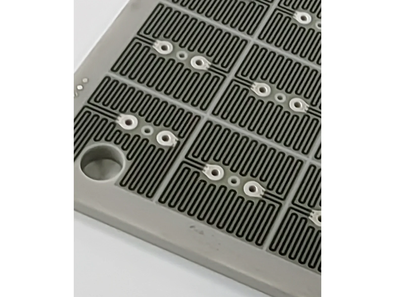
A 25-element AlN heater panel with repeated serpentine patterns and paired contacts. The supplied drawing specifies 350 Ω ±10% per element, 34 × 34 mm element geometry and an 8.0 mm substrate.
Verified capability review
The following values come from the supplied model drawing.
Reference drawing values do not replace an approved order revision or batch test record.
| Parameter | Product reference |
|---|---|
| Substrate | Aluminum nitride (AlN) |
| Element count / size | 25 elements; 34 × 34 mm each |
| Resistance | 350 Ω ±10% per element |
| Substrate thickness | 8.0 ±0.06 mm |
| Electrode thickness | 12 ±2 µm |
| Use-temperature reference | 80–250°C in the drawing |
Resolve these model-specific interfaces before confirming a sample or production order.
Keep the 34 mm element geometry separate from the full panel outline and mounting-hole pattern.
The drawing lists 25 individual 350 Ω elements. Supply the intended grouping and terminal scheme before a power review.
Specify the support surface, heat transfer, control method and temperature measurement locations.
Review each element resistance, terminal connection, insulation and the dimensional acceptance plan before shipment.
These are engineering review contexts, not customer project claims or application approvals.
Review individual element connections, sensor positions and zone-control requirements with the actual fixture.
Review application inputsUse the supplied AlN panel geometry when assessing thermal contact and mechanical support.
Review application inputsProvide the full assembly, power supply, duty cycle and qualification requirements for a model-specific review.
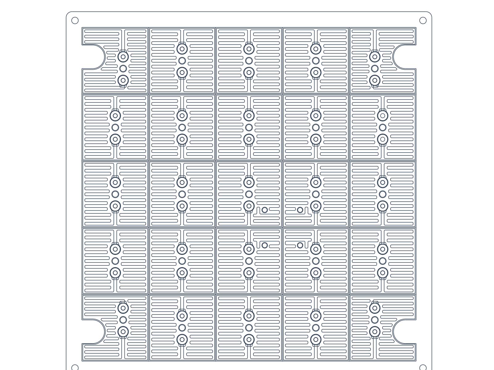
Review application inputsThe artwork extract below comes from the supplied model drawing.
The CAD view is a partial artwork extract for reference. It is not the complete manufacturing drawing or a dimensional inspection record; the approved order drawing controls every mechanical feature.
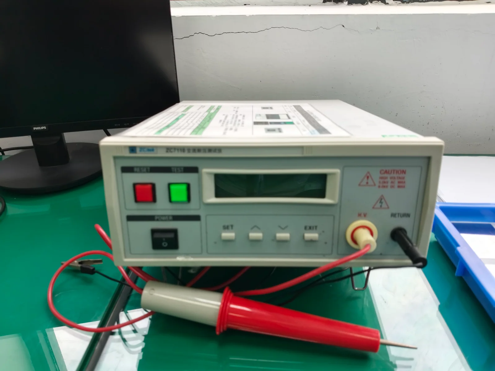
Screen printing and electrical inspection are supported by general company workshop photographs. They illustrate company capability and are not BH390A0 production-lot or test records.
Review manufacturing capabilities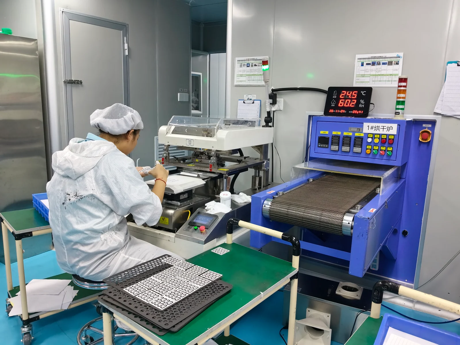
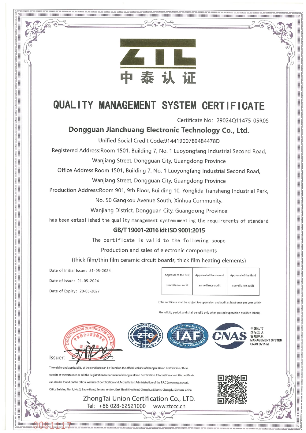
Company-level document only. Its holder, printed scope, dates and surveillance conditions govern applicability; it is not a test report for this model.
View certificateShort answers for quotation planning; released drawings and validation requirements remain controlling.
The drawing specifies 350 Ω ±10% for each of 25 elements. Overall behavior depends on the ordered connection arrangement; it must not be inferred from the panel photograph.
No. It is the individual element reference. The overall panel envelope, mounting pattern and edge features follow the detailed drawing.
It is a use-temperature reference in the supplied drawing. No lot-specific thermal test report was supplied with this release.
Provide the ordered panel drawing, element grouping, supply and loading targets, lead details, thermal fixture, control method, quantity and required tests.
Send the current part and assembly drawings with the selected variant, quantity and operating requirements. We will review the drawing-controlled interfaces and required evidence before confirming the quotation.
PDF, DWG, DXF, STEP, Gerber, ZIP, Excel, Word, or sample photos are accepted.
The drawing-upload form loads as you reach this section.