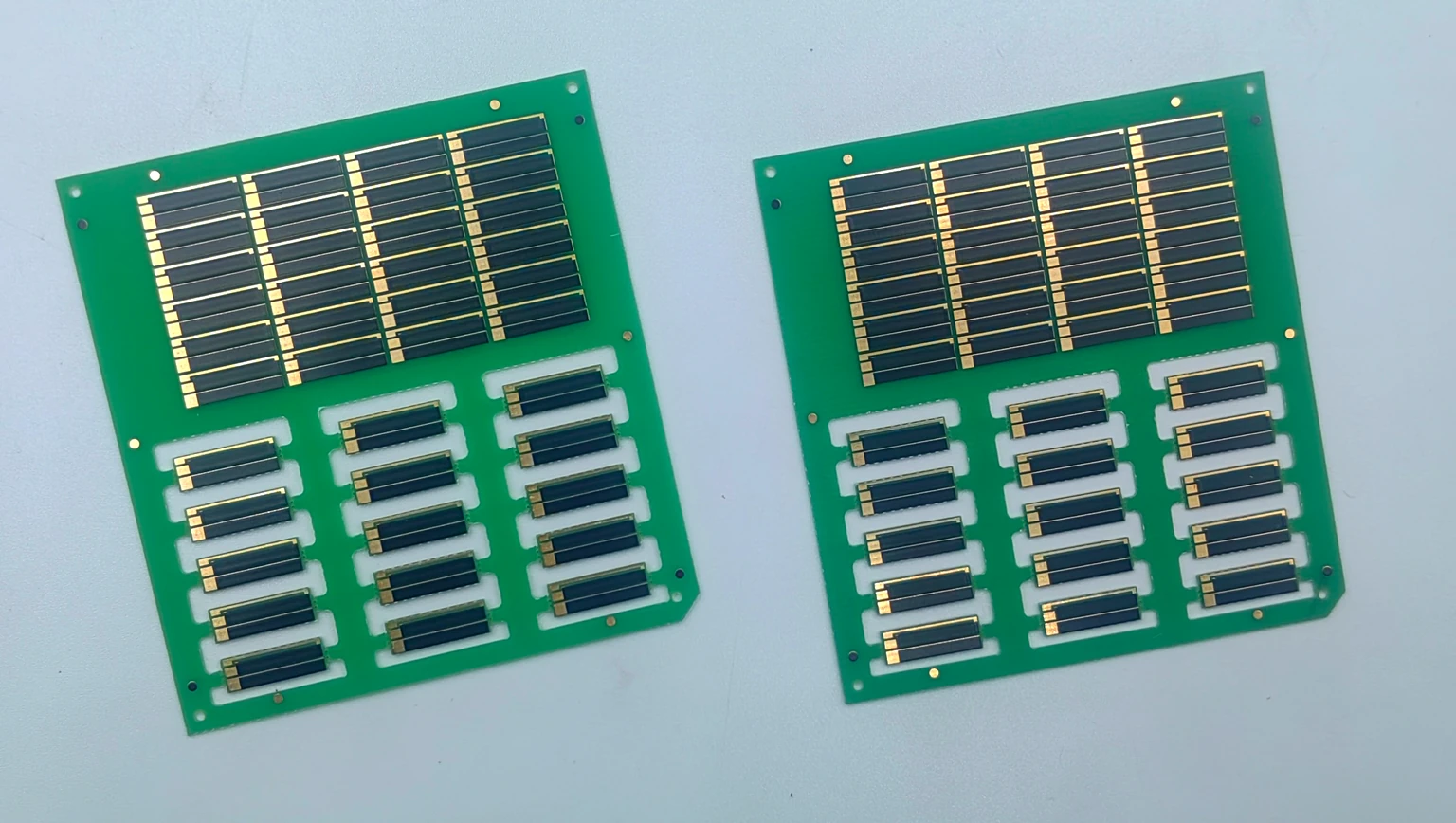
Track and contact alignment
Check printed edges, contact windows and overlap against the artwork. Inspect for unintended breaks or bridges.

FR4 printed resistor · BP320A0
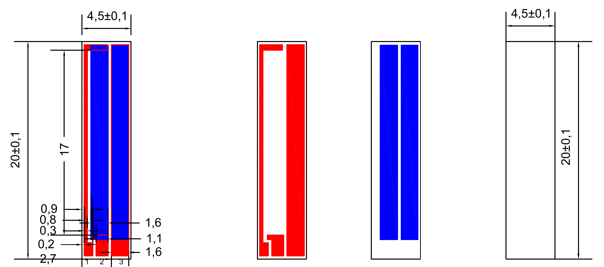
A single-sided FR4 resistor strip with two printed tracks and three terminal contacts. The BP320A0-1 drawing specifies a 20 × 4.5 mm outline and 20 kΩ ±15% between terminals 1 and 2. Review the contact arrangement below and send your assembly requirements for a quote.
Product reference
BP320A0-1 drawing reference.
| Parameter | Product reference |
|---|---|
| R(1–2) | 20 kΩ ±15% |
| Finished outline | 20 ±0.1 × 4.5 ±0.1 mm |
| Thickness | 0.5 ±0.1 mm |
| Material | Single-sided FR4 PCB |
| Contacts | 3 terminals: 1, 2, 3 |
| Printed tracks | 2 longitudinal tracks |
Four checks connect the drawing to your assembly.
Check printed edges, contact windows and overlap against the artwork. Inspect for unintended breaks or bridges.
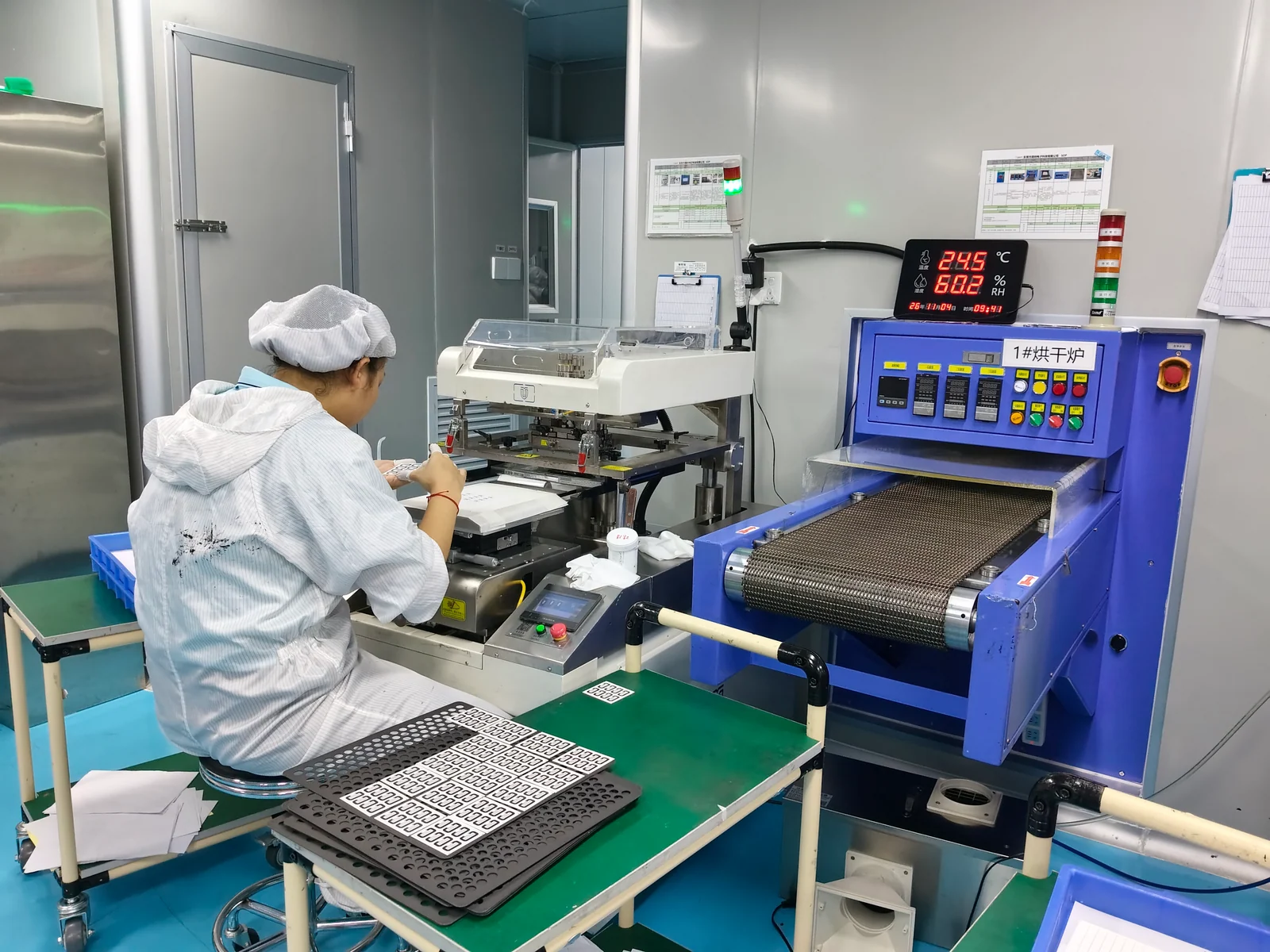
Use resistor printing and a compatible controlled cure. Keep the FR4 material route distinct from fired ceramic thick film.
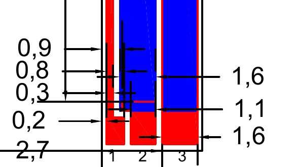
Measure 20 kΩ ±15% between terminals 1 and 2. Define terminal 3 and moving-contact tests separately.
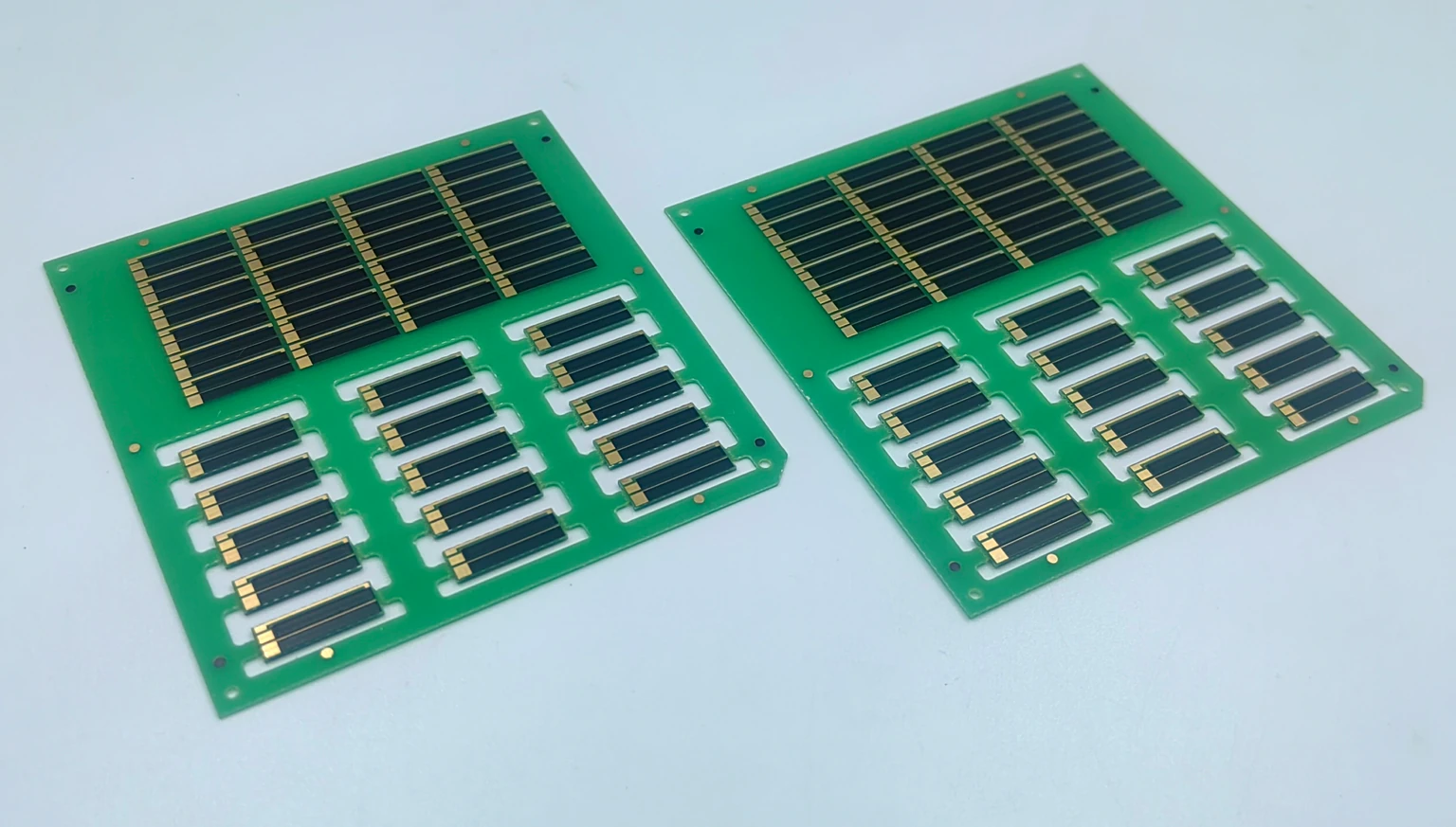
Use the 20 × 4.5 mm outline to check assembly clearance. Agree separation, edge condition and delivery form.
Selection depends on the complete contact assembly and its validation requirements.
Can be evaluated for linear feedback. Define stroke, wiper force and resistance response, then validate the complete assembly.
Discuss the contact interfaceMay suit a custom control slider. Review travel, end stops, contact loading and movement duty with the printed layout.
Review drawing inputsCan be reviewed for compact instruments. Specify connections, mounting, electrical loading and measurement limits before selecting the strip.
Explore the FR4 resistor familyBP320A0-1 drawing reference, with the contact end at the bottom. Open the drawing to inspect dimensions and layer alignment.
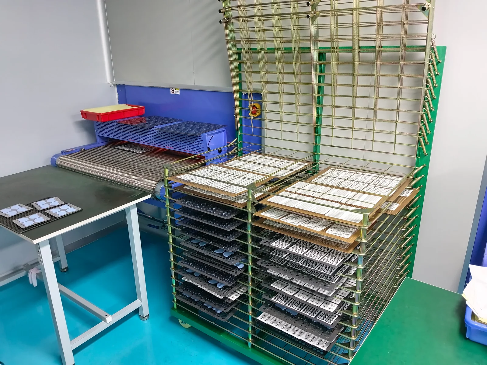
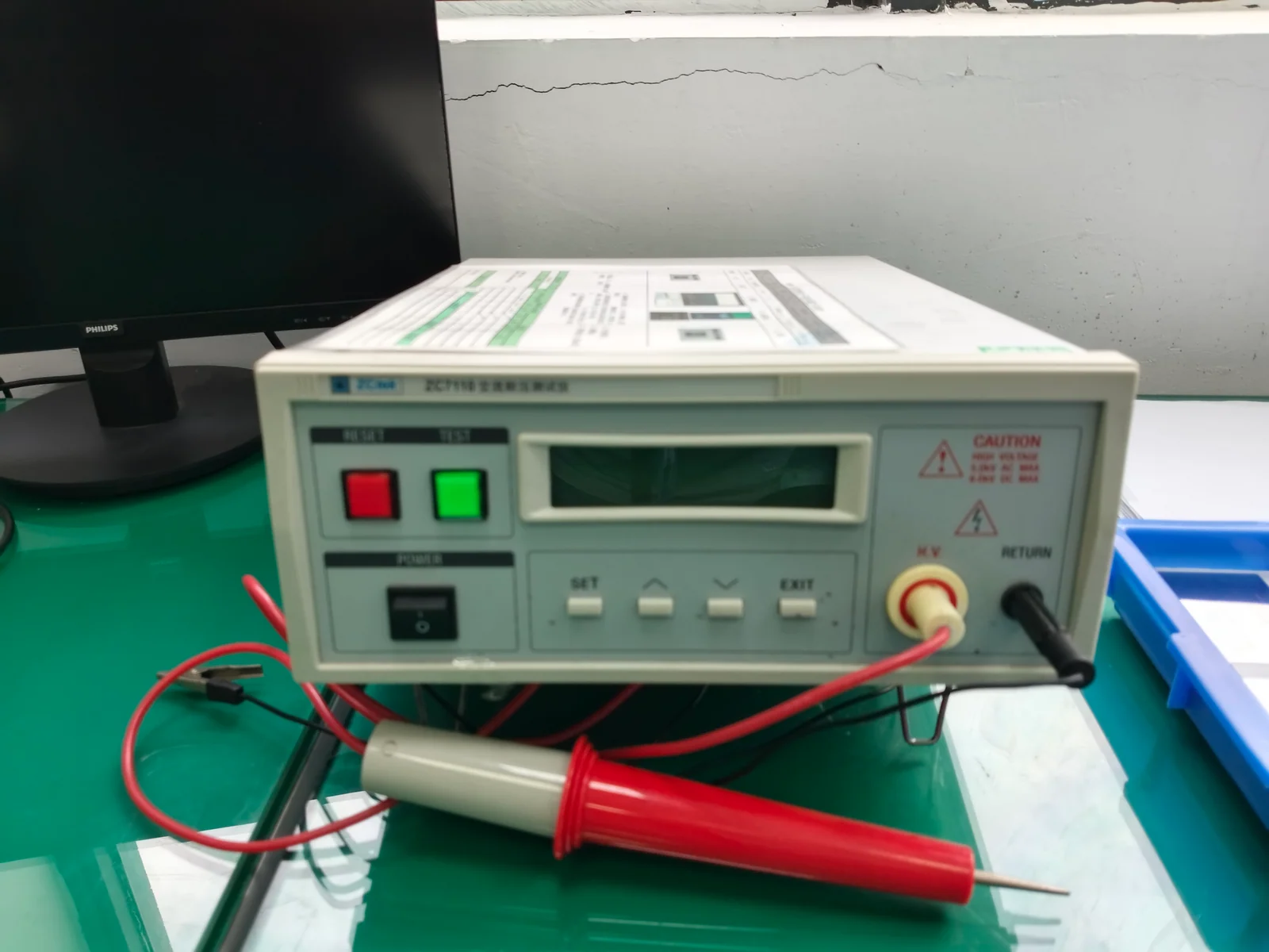
Our Dongguan facility includes screen-printing workstations, optical measurement equipment and electrical test benches. BP320A0 production and inspection are planned against the approved drawing. These photographs show our general facilities.
See our manufacturing capabilities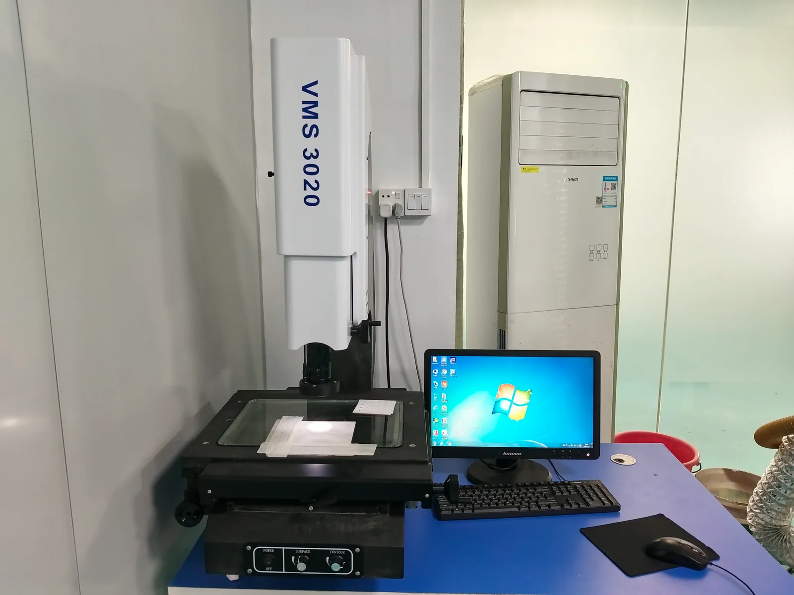
Short answers for quotation planning; released drawings and validation requirements remain controlling.
It applies between terminals 1 and 2 and gives a reference acceptance range of 17–23 kΩ. It does not define resistance involving terminal 3 or a moving-contact response curve. Use the numbered drawing orientation and agree the measurement method and conditions with your order.
The selected BP320A0-1 drawing specifies 20 ±0.1 mm length, 4.5 ±0.1 mm width and 0.5 ±0.1 mm thickness. The photographs and video show manufacturing panels. Specify individual strips or panels in your RFQ, together with the drawing revision, quantity, edge condition and packing requirements.
It can be evaluated with a sliding-contact design. Provide the wiper material, force, stroke, movement duty and operating environment. Wear life, contact noise and response accuracy must be established with the complete assembly and agreed tests; those ratings cannot be inferred from photographs of the panel.
No. BP320A0 uses an FR4 board with a printed resistor layer and controlled curing. Ceramic thick film uses a different substrate and material process. Do not transfer ceramic firing temperatures or operating ratings to this FR4 part. Provide the actual operating and assembly conditions when requesting a quote.
Attach your assembly drawing or sample photos. Include quantity, contact arrangement and resistance requirements so we can review fit, measurement and delivery.
PDF, DWG, DXF, STEP, Gerber, ZIP, Excel, Word, or sample photos are accepted.
The drawing-upload form loads as you reach this section.