BS391A0 · Drawing-led manufacturing

BS391A0 Square Stainless Steel Heater

A square stainless steel heater with serpentine tracks, six main mounting openings and a central opening. The BS391A0-1 drawing defines a 3 mm substrate and a 2.5 kW reference at 25°C.

443 stainless
Drawing substrate
3.0 ±0.1 mm
Substrate thickness
2500 W ±10%
Drawing reference at 25°C
19.36 Ω
Nominal drawing resistance
Product Categories

Verified capability review

Drawing reference and quotation inputs

The following values come from the supplied model drawing.

Reference drawing values do not replace an approved order revision or batch test record.

ParameterProduct reference
Drawing referenceBS391A0-1
Substrate443 stainless steel; 3.0 ±0.1 mm
Electrical reference380 V Y-connected system; 220 V actual load
Power at 25°C2500 W ±10% drawing reference
Resistance19.36 Ω nominal; 17.42–21.3 Ω drawing range
Dielectric test requirementAC 1250 V, leakage <5 mA, 3 s
Drawing, measurement and acceptance details
Drawing reference
BS391A0-1. Only the model-specific revised requirement block is used; unrelated older reference notes are excluded. Drawing requirement; final release follows the ordered revision and inspection plan.
Substrate
443 stainless steel; 3.0 ±0.1 mm. Review flatness, finish and the mounting interface on the released drawing. Drawing requirement; final release follows the ordered revision and inspection plan.
Electrical reference
380 V Y-connected system; 220 V actual load. Retain the system and heater-load values separately. The ordered wiring diagram controls the assembly. Drawing requirement; final release follows the ordered revision and inspection plan.
Power at 25°C
2500 W ±10% drawing reference. Performance depends on the released electrical and thermal assembly; no lot test is implied. Drawing requirement; final release follows the ordered revision and inspection plan.
Resistance
19.36 Ω nominal; 17.42–21.3 Ω drawing range. Resistance marking and grouping are specified at shipment in the drawing. Drawing requirement; final release follows the ordered revision and inspection plan.
Dielectric test requirement
AC 1250 V, leakage <5 mA, 3 s. This is an acceptance requirement in the drawing, not evidence that this photographed unit was tested. Drawing requirement; final release follows the ordered revision and inspection plan.
Mounting geometry
Six main openings and a central opening. Position, hardware, clamp load and clearances follow the detailed assembly drawing. Drawing requirement; final release follows the ordered revision and inspection plan.
General tolerance
±0.1 mm where unmarked. Individually marked dimensions take precedence. Drawing requirement; final release follows the ordered revision and inspection plan.

BS391A0 engineering and inspection review

Resolve these model-specific interfaces before confirming a sample or production order.

Electrical reference and connection

Resolve the Y-connected system, actual heater-load voltage and resistance grouping with the assembly drawing.

Mounting and thermal contact

Review the mounting-hole positions, flatness, contact pressure and heat-transfer surface together.

Printed-layer integrity

Protect the dielectric, serpentine paths and terminal areas during handling and assembly.

Release inspection

Agree resistance marking, dimensional inspection and the specified dielectric acceptance test with traceable records.

Assembly contexts to review

These are engineering review contexts, not customer project claims or application approvals.

View application guides

Supplied product and drawing evidence

The artwork extract below comes from the supplied model drawing.

The CAD view is a partial artwork extract for reference. It is not the complete manufacturing drawing or a dimensional inspection record; the approved order drawing controls every mechanical feature.
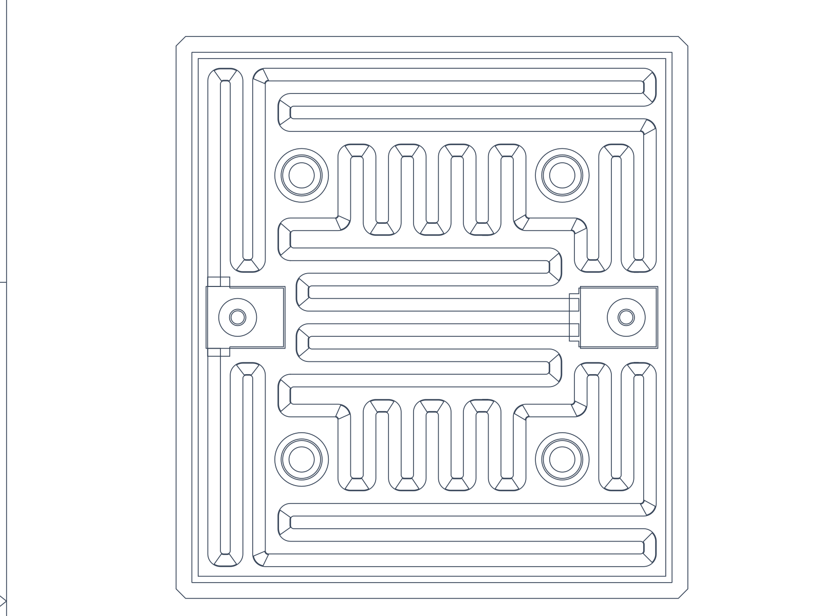
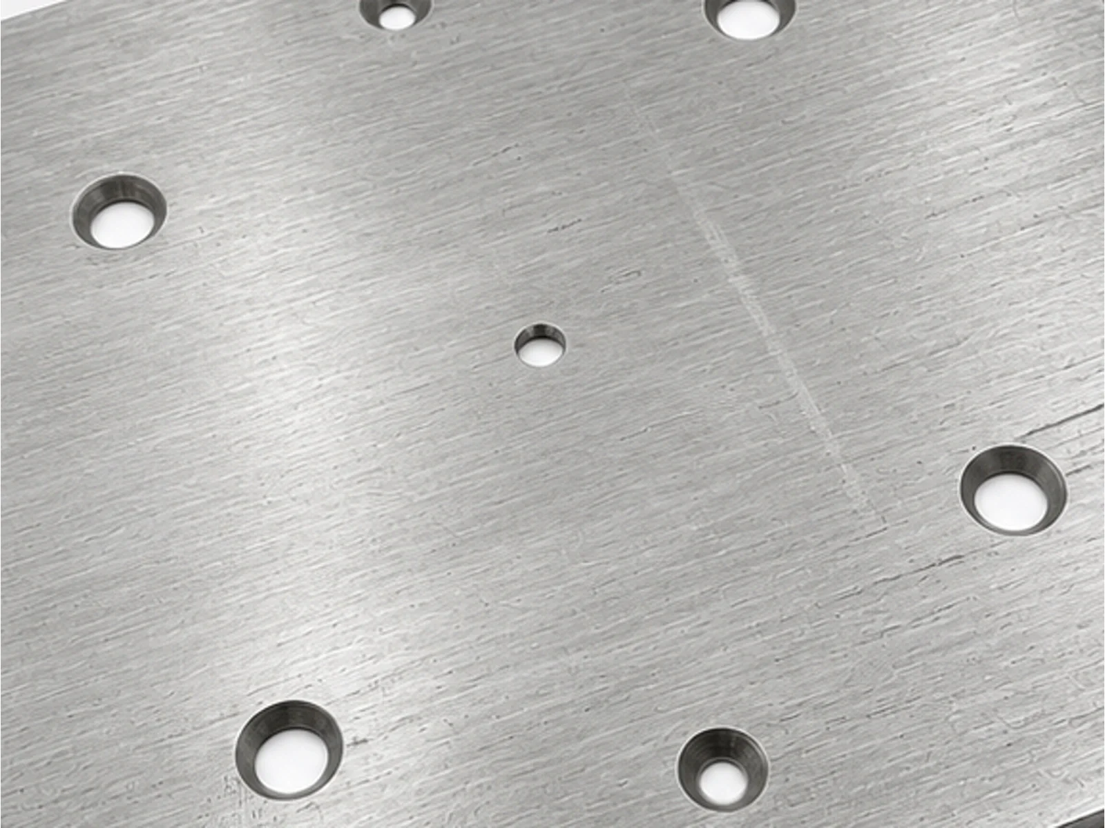
BS391A0 source CAD geometry crop
Source CAD geometry
BS391A0: Crop from the color-corrected rear photo showing existing mounting features
Actual product detail
Reference basis
Values on this page are transcribed from the supplied BS391A0 drawing and scoped to its selected variant.
Photographic treatment
Source geometry is preserved. Selected bare stainless surfaces are cosmetically color-corrected to bright silver; photo crops are not new product angles.
View 2 additional evidence boundaries
Inspection evidence
Drawing acceptance requirements and thermal targets are not presented as completed batch tests. Request the agreed inspection records with your order.
Unconfirmed conditions
Material-stack details, assembly interfaces, operating duty and validation conditions not fixed in the selected drawing remain subject to application review.

Manufacturing and inspection capability

Screen printing and electrical inspection are supported by general company workshop photographs. They illustrate company capability and are not BS391A0 production-lot or test records.

Review manufacturing capabilities
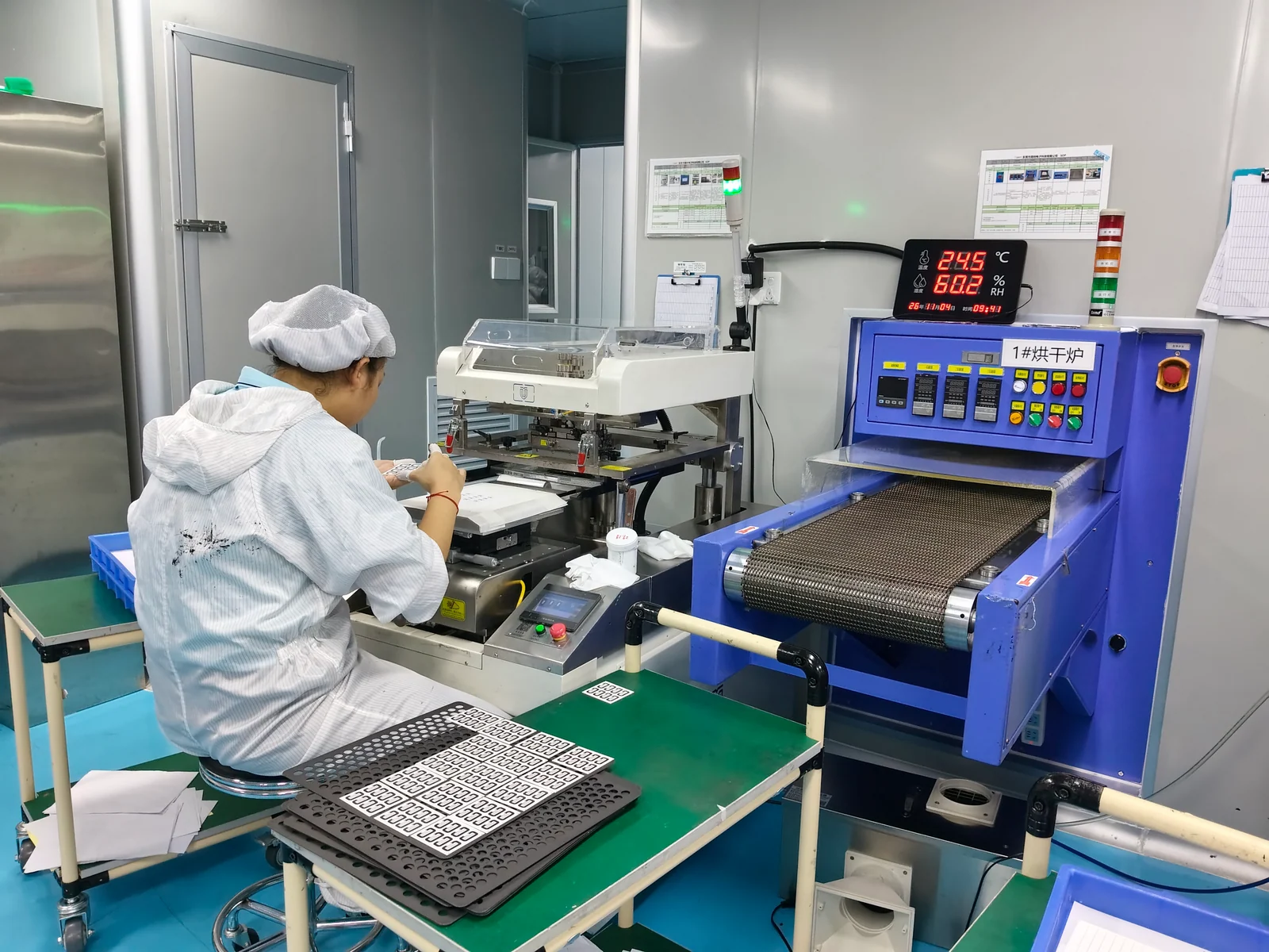
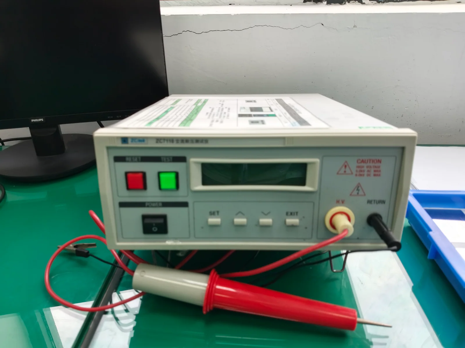
Company screen-printing workstation
Screen-printing workstation
Company electrical inspection bench
Electrical inspection bench

Company quality document

Original company ISO 9001 certificate preview
Company document

ISO 9001 certificate

Company-level document only. Its holder, printed scope, dates and surveillance conditions govern applicability; it is not a test report for this model.

View certificate

Technical FAQ

Short answers for quotation planning; released drawings and validation requirements remain controlling.

Which resistance reference is used on this page?

The model-specific BS391A0-1 requirement block gives 19.36 Ω nominal and a 17.42–21.3 Ω reference range. Unrelated older notes elsewhere in the CAD file are not used as this model rating.

Why are both 380 V and 220 V shown?

The drawing distinguishes a 380 V Y-connected system from a 220 V actual heater load. These are separate references and the released assembly wiring diagram is controlling.

Are the dielectric figures measured results?

No. AC 1250 V, leakage below 5 mA and a 3-second duration are drawing acceptance requirements. A batch test record must be agreed separately.

What should be sent for a quotation?

Send the BS391A0-1 revision, mounting drawing, electrical configuration, thermal interface, target duty, quantity and required inspection evidence.

Request a BS391A0 quotation

Send the current part and assembly drawings with the selected variant, quantity and operating requirements. We will review the drawing-controlled interfaces and required evidence before confirming the quotation.

RFQ inputs and review sequence
  • Model and revision stay attached to the inquiry.
  • Acceptance requirements are agreed before sample release.
  • Current BS391A0 part drawing, variant and assembly drawing.
  • Material stack, contact or terminal requirements and mating interface.
  • Electrical and thermal targets, control method and operating environment.
  • Prototype and production quantities, schedule, required tests and packing.
  1. 1Send the drawing and assembly requirements.
  2. 2Resolve dimensions, interfaces, loading and inspection scope.
  3. 3Confirm the quotation and sample acceptance plan.

Submit RFQ and upload files

PDF, DWG, DXF, STEP, Gerber, ZIP, Excel, Word, or sample photos are accepted.

The drawing-upload form loads as you reach this section.