
On this page
- Build a Functional Constraint Map
- Place Resistors for Matching and Trim Access
- Design Overlaps and Registration Margins by Layer
- Protect Current Paths and Joining Pads
- Plan Inspection Before Final Routing
- A Worked Engineering Review
- Design Review Checklist
- Questions Engineers Commonly Ask
- Related Engineering Resources
- Closing Note
Prepared by Chipsimple Engineering Team, Engineering and technical content review
Published online August 10, 2026 · Reviewed August 10, 2026
ENGINEERING ARTICLE 04 / VOLUME 1
Turning a Schematic into a Manufacturable Thick Film Layout
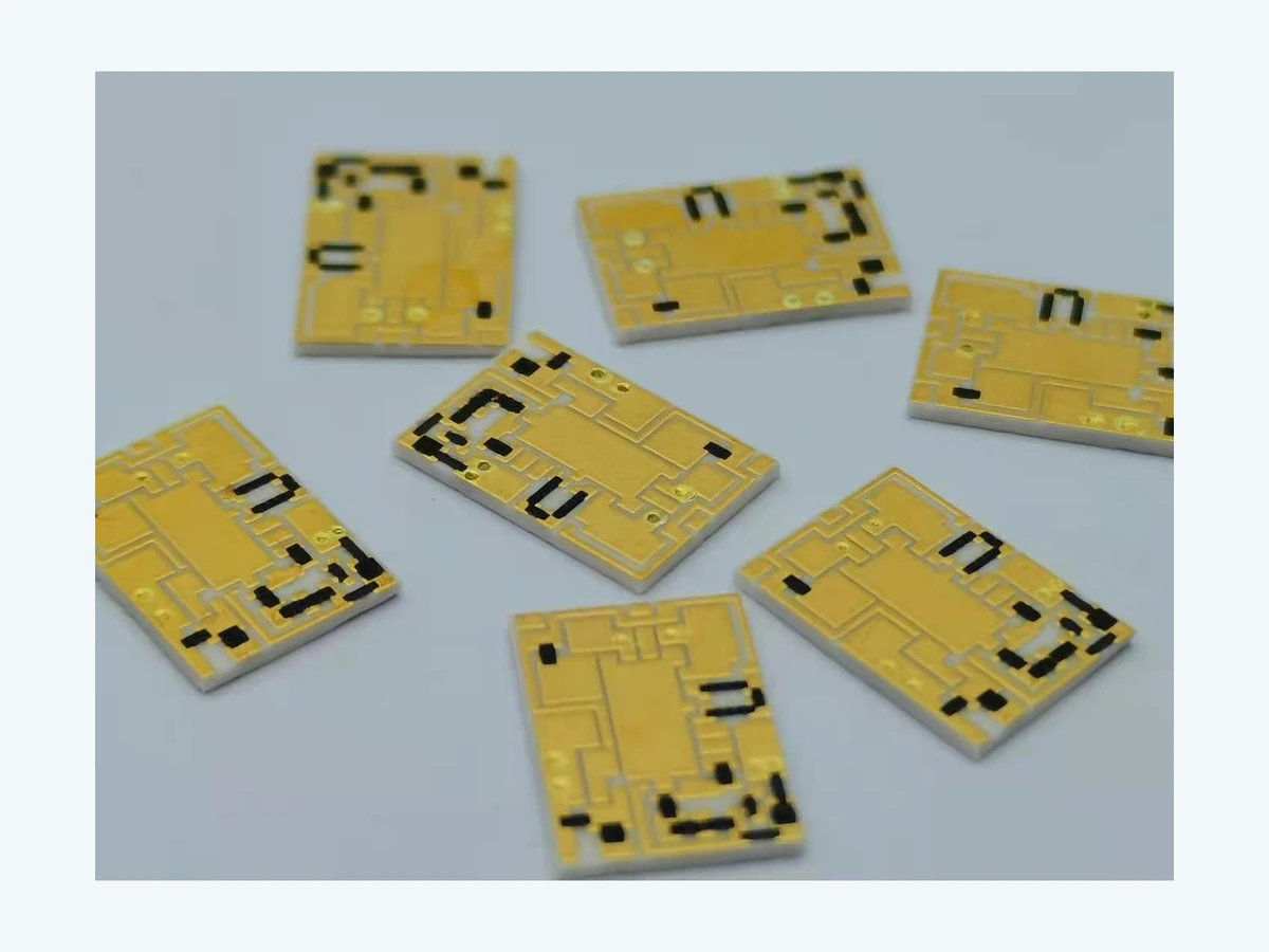
The first layout pass should identify the characteristics that can fail the product: resistor ratio, high-current path, high-voltage spacing, sensitive node, hot component, joining pad and mechanical datum. Those features are placed and protected before convenient routing begins. A later design-for-manufacture review then checks every layer against the actual print-and-fire sequence and the available inspection access.

Build a Functional Constraint Map
In a stable manufacturing route, not every net and component deserves the same geometric margin. This means high-voltage, high-current, high-impedance and ratio-sensitive sections fail through different mechanisms. The observation is especially useful because it connects a visible feature to an electrical, thermal or mechanical consequence.
The control plan should colour-code or classify nets by electrical stress, tolerance and inspection need before routing. It should also name the drawing characteristic or coupon that represents the requirement, avoiding an instruction that depends on personal interpretation.
Evidence comes from a design review that traces each critical characteristic from schematic requirement to physical feature. A trend across position or lot is usually more valuable than a perfect reading from one hand-picked sample.
Investigate using one generic spacing or width rule for functions with very different consequences. The pattern may identify a narrow process interaction long before the final circuit becomes an open, short or out-of-tolerance value.
Place Resistors for Matching and Trim Access
A useful way to frame the decision is this: Resistor orientation and thermal environment influence tracking. As a result, matched elements separated by a heat source or printed in different process directions can develop avoidable ratio error. That cause-and-effect chain should remain visible when thick film circuit layout design is reviewed with purchasing and quality teams.
The manufacturing boundary is protected when the team can group related resistors, align geometry where practical and keep a clear optical path for measurement and trimming. This approach separates the customer's functional need from the supplier's machine-specific compensation.
Confirm the decision with network data by substrate position before and after trim and thermal exposure. Include both typical and boundary-condition specimens where the failure consequence justifies them.
The symptom perfect nominal values at room temperature with poor ratio stability under load deserves a structured investigation. Check material lot, artwork position, thermal history and measurement setup before assigning a single cause.
Design Overlaps and Registration Margins by Layer
Geometry and material meet at this point: Printed layers do not register with photolithographic precision. Therefore, conductor-to-dielectric overlaps, via lands and crossover windows require margin for screen, substrate and firing variation. A nominal specification that omits the interface is incomplete even if every individual value looks reasonable.
During release, define minimum functional overlap and let artwork include the qualified registration allowance. Make sure the acceptance method measures the same physical feature that the design calculation assumed.
Useful confirmation includes overlay inspection on first articles and sectioning where a buried interface is critical. Keep photographs or sections tied to part, revision, lot and orientation so they remain evidence rather than decoration.
One failure signature is exposed conductor edges, reduced via capture or dielectric coverage that looks acceptable from one side. It often becomes clear only when results are sorted by position, process stage or exposure instead of being combined into one average.
Protect Current Paths and Joining Pads
Process capability follows from the mechanism: The narrowest conductive neck and weakest interface often set the circuit limit. The direct implication is that routing that is electrically continuous may still overheat, leach during soldering or crack at a rigid terminal. This makes the topic a design input, not merely a factory setting adjusted after the drawing is complete.
A practical release action is to size paths for current and pulse duty, widen transitions and specify the intended joining process at each pad family. The requirement should survive staff changes and future lot reviews because it is recorded with the controlled construction.
Use conductor resistance, temperature rise, adhesion and assembly pull or shear evidence to demonstrate margin. When feasible, compare the result before and after the operation most likely to disturb it.
Pay attention to local discoloration, pad erosion or intermittent opens near an otherwise generous conductor. A corrective action is credible only when it changes that physical mechanism and the follow-up data confirm the change.
Plan Inspection Before Final Routing
A buried or obstructed feature cannot be inspected by wishful thinking. The consequence is that test points, optical access and coupon locations influence whether process variation can be separated from assembly variation. In a thick film circuit layout design review, this relationship deserves an explicit decision rather than an assumption copied from a previous drawing.
The practical control is to reserve probe lands, witness coupons and sight lines while the layout can still move. That instruction should be linked to the layer, material system or feature it governs so that production and inspection read it in the same way.
Verification should include an agreed control plan linking each critical feature to a measurable characteristic. If the evidence is collected only after final assembly, the team loses the ability to separate printing, firing, trimming and assembly effects.
A common warning sign is discovering at pilot build that the critical node is inaccessible or the only evidence requires destructive analysis. Treat that symptom as a request to examine the process chain, not simply as a reason to widen the final tolerance.
A Worked Engineering Review
For a two-layer heater controller, begin with the high-current heater path and the temperature-sense network. Place the sense resistors away from the hottest conductor and keep the matched pair in a similar orientation. Define the dielectric crossover only after the conductor widths and voltage spacing are stable. Add sufficient overlap around the crossover, then reserve a probe point before the protective layer is drawn. Finally, walk the manufacturing sequence layer by layer: clean, print, dry, fire, inspect, print the next layer, trim, assemble and test. Any feature that becomes inaccessible too early should be redesigned or given a coupon.
Design Review Checklist
- Classify nets by voltage, current, impedance and tolerance.
- Place matched and trimmable resistors before routine routing.
- Apply registration and overlap rules for every printed layer.
- Identify joining metallurgy and mechanical load at each pad.
- Reserve test access, coupons and inspection sight lines.
Questions Engineers Commonly Ask
Should the customer drawing contain screen compensation?
Normally the drawing should state the functional geometry and tolerances. Screen and firing compensation are manufacturing controls that the qualified supplier applies to its own process unless the artwork itself is the controlled deliverable.
How early should the manufacturer review the layout?
Before tooling release and preferably before routing is frozen. Early review can move critical features; late review can only request exceptions or a redesign.
Are generic PCB design rules suitable for thick film?
They are a starting language, not a complete rule set. Printed paste, firing, ceramic handling, resistor trimming and joining interfaces need process-specific allowances.
Related Engineering Resources
Closing Note
A good thick-film layout makes the process sequence visible. It provides margin where variation is physical, access where evidence is needed and clear notes where the assembly interface controls reliability.