
Overview
Resistor noise and stability are different time-dependent behaviors that must be specified with bandwidth, bias, temperature, loading, environment and observation interval. Thermal noise follows resistance and temperature, while excess noise can depend on material microstructure, electric field, geometry, terminations and contacts. Stability includes reversible temperature response, short-term settling, humidity/bias effects, assembly shift and longer-term drift. A quiet initial reading does not prove stability, and a stable average can hide objectionable noise. The complete printed resistor, protection, substrate, circuit and measurement chain must be evaluated under application conditions.
Failure controls
These are review prompts, not evidence that every risk applies or that every test is available.
- A
Quoting noise without bandwidth, bias, temperature, circuit and instrument floor.
- B
Confusing Johnson noise, excess noise, interference and contact events.
- C
Calling short settling data long-term stability.
- D
Ignoring trim, protection and assembly shifts.
- E
Comparing supplier coupons with different methods as product guarantees.
- F
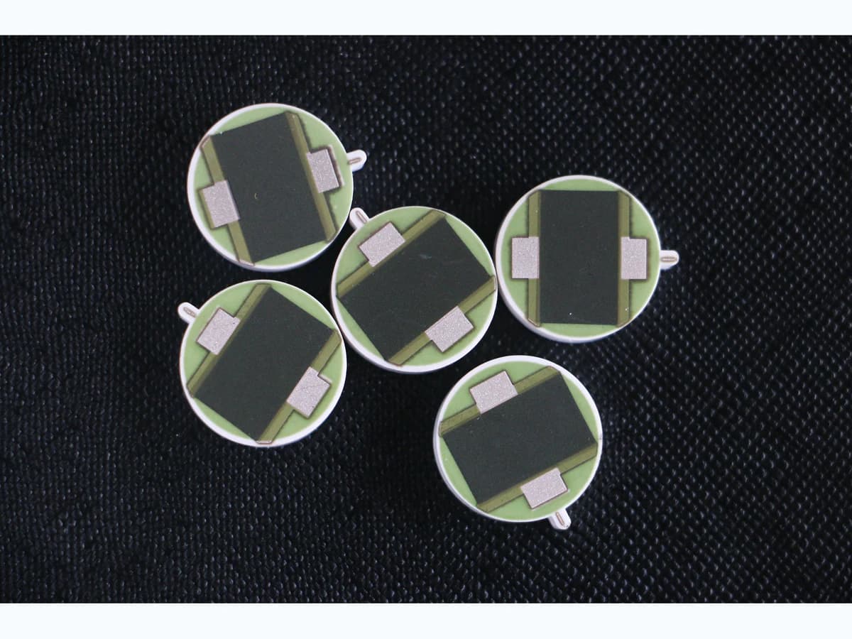
Using a photograph as precision, noise, drift or life evidence.
Controlled model
Noise and stability budget
Keep fundamental thermal noise, excess noise, instrument noise and time-dependent resistance change separate. State bandwidth, filtering, bias, source/load and temperature for every result.
v_n,rms = √(4 k T R B)Johnson-noise voltage of an ideal resistor over bandwidth.
- Units
- V rms
- Use boundary
- Assumes equilibrium, resistive impedance and stated effective bandwidth; excludes excess noise, contacts, amplifier noise and interference.
ΔR/R₀ = (R_t − R₀)/R₀Fractional resistance change between controlled reference measurements.
- Units
- Dimensionless
- Use boundary
- Reference temperature, voltage, timing, recovery, fixture and uncertainty must match; change does not identify mechanism.
Decision comparison
| Decision | Route A | Route B | Verification |
|---|---|---|---|
| Low-noise material versus lower-power geometry | A candidate material may show favorable supplier noise data under its coupon method but still respond differently in product geometry. | Longer or wider geometry may reduce field or self-heating but changes area, terminations, parasitics and process sensitivity. | Compare named candidates with identical circuit boundary, bandwidth, bias, temperature, trim, protection and exposure. |
| Trim correction versus as-fired design | Trimming reaches initial value but creates a local edge and field/current redistribution whose settling and protection matter. | As-fired design avoids a cut but may need broader initial tolerance or different geometry/material control. | Measure spectra and resistance before/after trim, protection, assembly and environmental stages. |
- A single peak-to-peak trace without acquisition bandwidth, duration, filtering, setup and interference controls is not comparable evidence. Aging, humidity/bias, thermal cycling, soldering, bonding, encapsulation and mechanical stress must be considered separately from initial tolerance.
- A meaningful stability program uses repeated reference measurements that return the resistor to the same stated temperature, bias level, fixture, contact method, stabilization time and instrument configuration. In-stress readings, immediate recovery readings and later recovered readings answer different questions and should not be merged. Network applications should retain both absolute element values and the loaded transfer or ratio because common movement can cancel in one result while still changing input impedance, dissipation or interaction with the source. When a spectrum or drift curve changes, investigation should preserve the device location, material lot, panel position, trim image, protection state, assembly history and exposure sequence so the observation can be connected to a physical cause instead of averaged into an unsupported generic limit.
Noise-and-stability workflow
The order makes assumptions and ownership visible before a result is promoted to a requirement.
- 01
Define circuit sensitivity
Specify resistance, ratio, source/load, signal level, bias, bandwidth, filtering, sample rate, noise metric, drift interval, reference temperature, warm-up, calibration and total error budget.
- 02
Select material and geometry
Review named resistance decade, TCR, VCR, supplier noise method, fired length/width, terminations, trim, power, field, substrate, conductor and protection without transferring typical values.
- 03
Control measurement interference
Define shielding, grounding, guarding, fixture, contacts, amplifier, instrument floor, aliasing, line interference, vibration, temperature, humidity and acquisition/analysis method.
- 04
Establish staged baselines
Measure after firing, trim, protection, assembly and stabilization using identical reference conditions; preserve raw time and frequency records and measurement uncertainty.
- 05
Apply representative stress
Use actual bias, power, temperature, humidity, cycling, assembly heat, mechanical state and time; separate in-stress response, recovery and permanent change.
- 06
Freeze acceptance and changes
Tie limits to bandwidth, state, interval, material, geometry, process, trim, protection, assembly, sampling and requalification triggers.
Engineering review matrix
Each row links a design variable to evidence that can support a drawing or release decision.
| Variable | Control question | Verification route |
|---|---|---|
| Noise metric and bandwidth | Define spectral density, RMS or peak-to-peak method, frequency limits, filters, duration, sample rate and window. | Report raw spectrum/time series and verified instrument floor under the same setup. |
| Bias and electric field | Set voltage/current, polarity, waveform, dwell, source/load and local geometry. | Capture actual bias and compare noise at controlled levels while monitoring temperature. |
| Material and geometry | Name paste series, substrate, conductor, fired dimensions, terminations, firing/refires and lot. | Correlate geometry/material identity with noise and resistance data. |
| Power and temperature | Define self-heating, ambient, mounting, gradients, warm-up and neighboring sources. | Measure at fixed thermal states and separate TCR-driven change. |
| Trim and protection | Set trim cut, remaining path, settling, overglaze/overcoat, refire and assembly sequence. | Compare each stage and inspect cuts/protection after exposure. |
| Environment and time | Define humidity/bias, cycling, chemicals, vibration, storage, aging and recovery intervals. | Use configuration-linked interval data and failure observations. |
| Measurement uncertainty | Allocate contacts, instruments, references, drift, repeatability, interference, processing and decision rule. | Run controls and report uncertainty with every acceptance result. |
Reference boundary
Public method sources
These sources support the engineering method and terminology used in this technical guide. They do not establish a ThickFilmPCB material list, capability limit, customer result, certification, or finished-product specification.
- 01IEC 60115-1:2020 — Fixed resistors
Supports resistor characteristic and test terminology; no ChipSimple noise or stability value follows.
- 02Vishay — Basics of Linear Fixed Resistors
Supports manufacturer terminology for resistor noise, loading and stability; it is not product evidence for this site.
- 03Heraeus R8900 resistor system data sheet
Supports one named system's stated test context only; typical values are not transferable.
Inputs for a practical review
Unknown values may be labelled unknown. The review should convert uncertainty into an explicit decision or validation task.
Send Drawings- 01
Circuit, values, ratios, source/load, signal, bias and error budget.
- 02
Noise metric, bandwidth, filtering, sampling, duration and instrument method.
- 03
Material, geometry, terminations, trim, protection, firing and assembly.
- 04
Power, voltage, temperature, mounting, warm-up and gradients.
- 05
Humidity/bias, cycling, chemicals, vibration, aging and recovery.
- 06
Stability intervals, acceptance, uncertainty, raw data and sampling.
- 07
Prototype variants, traceability, revisions, substitutions and reviewers.