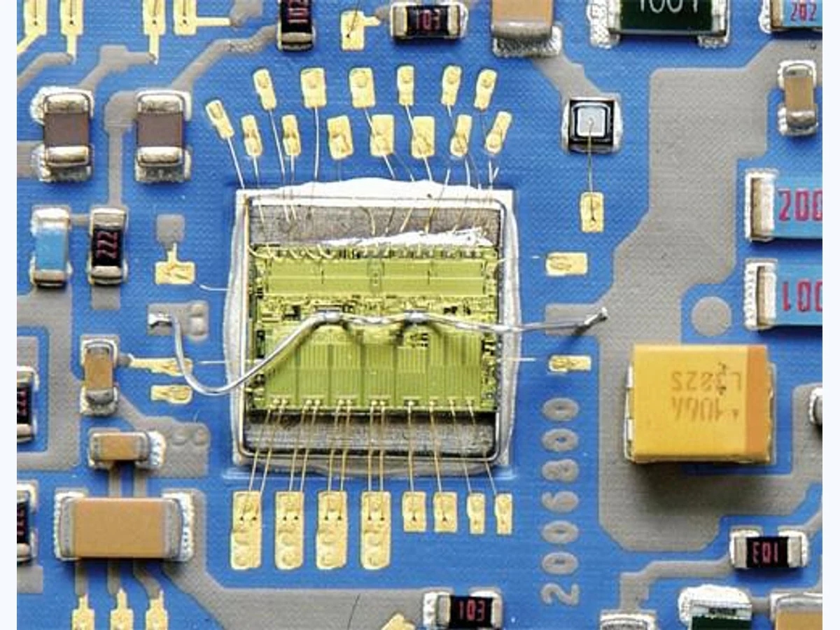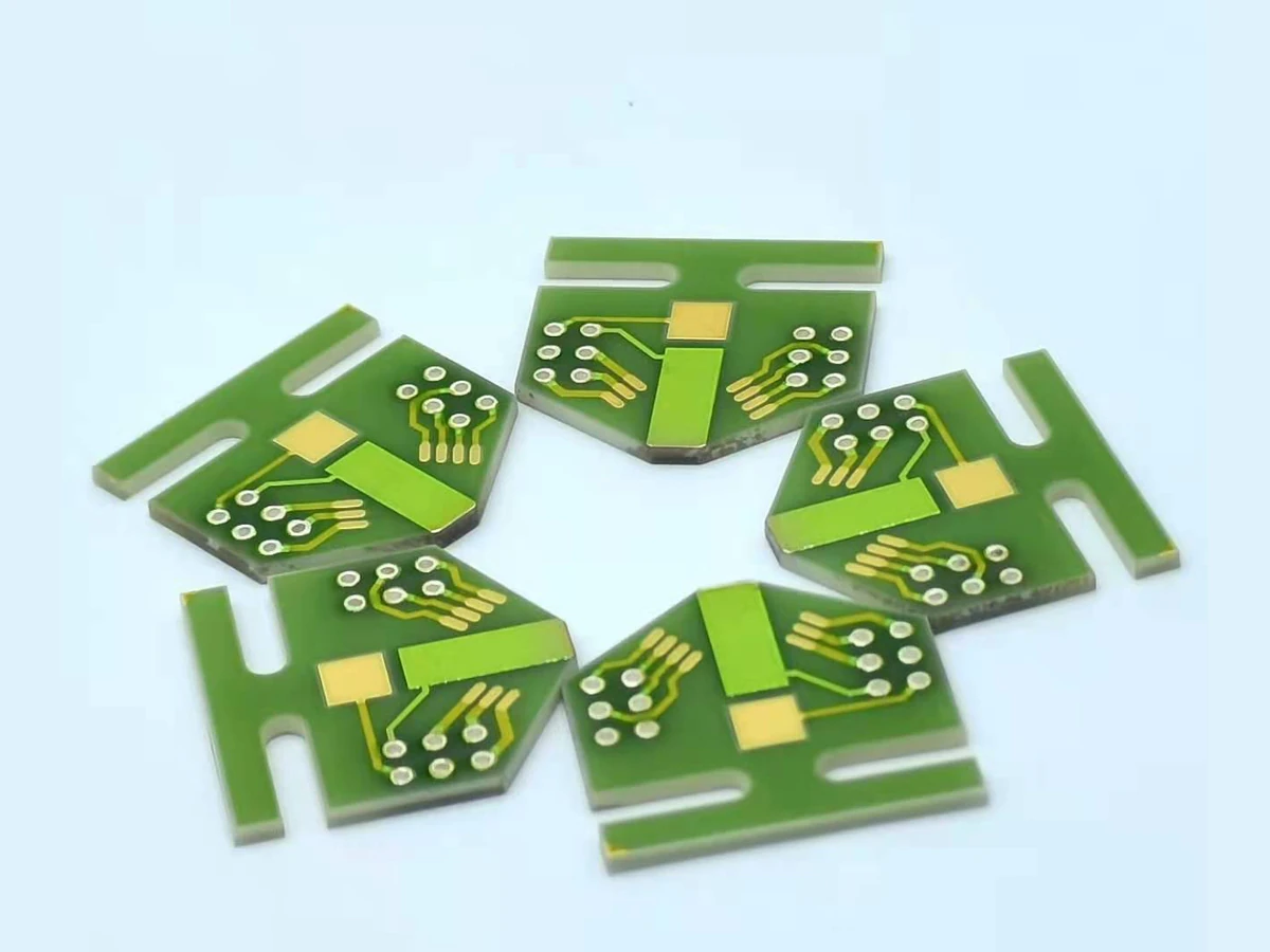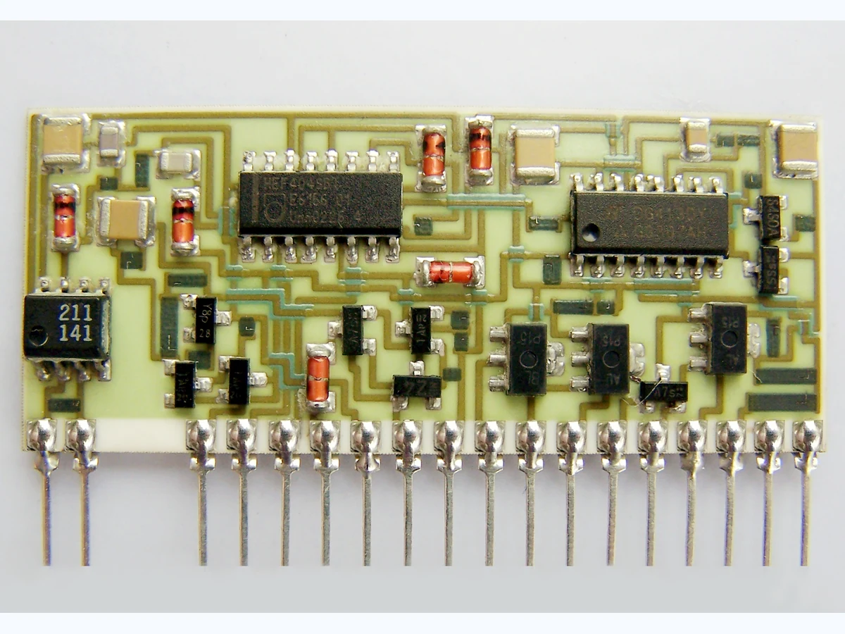
A ceramic circuit thermal model is most useful when it separates each heat-flow bottleneck: source-to-substrate attachment, ceramic spreading, interface material, housing and ambient cooling. That chain shows where a design change can actually reduce temperature.
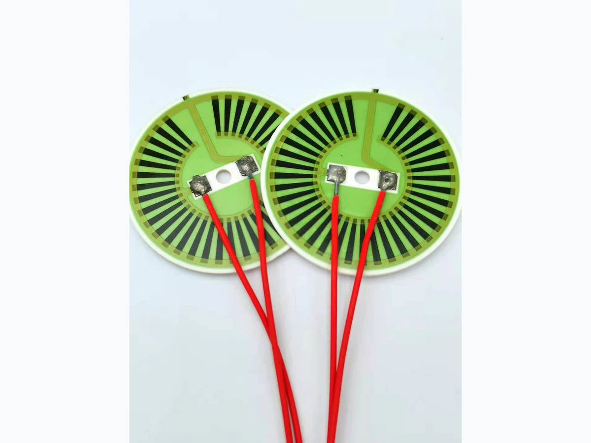
The 45-degree heat-spreading model is a useful hand calculation for estimating how heat area grows through a ceramic layer. It is not a law of heat flow and should be checked when geometry, boundaries or multiple sources make the assumption weak.
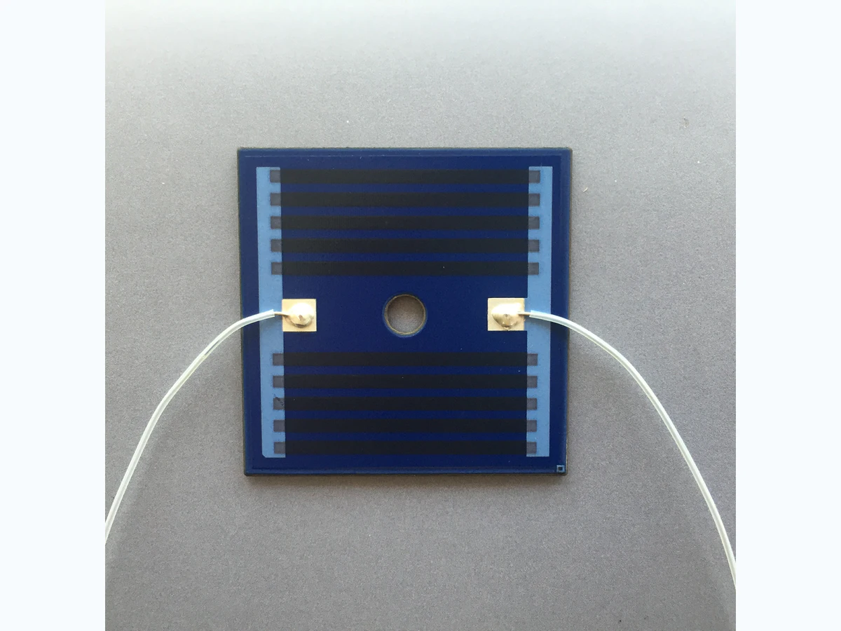
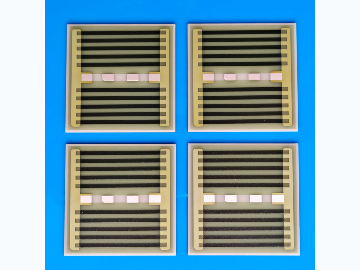
A thick-film heater should be designed from the load, temperature uniformity and cooling conditions backward to resistance geometry. Nominal resistance alone cannot define watt density, hot spots, control response or thermal-cycle life.
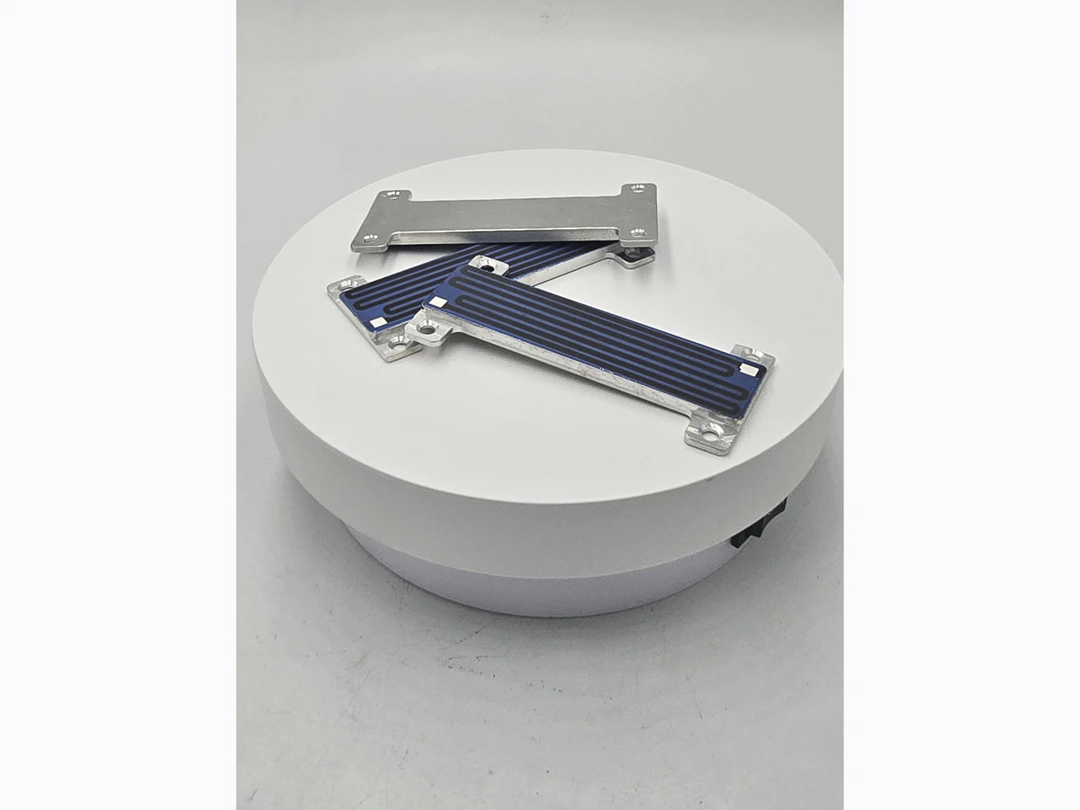
Thermal cycling repeatedly strains ceramic, printed films, solder, adhesives and terminals because their coefficients of thermal expansion differ. Reliability improves when the layout and assembly give that strain a controlled path.
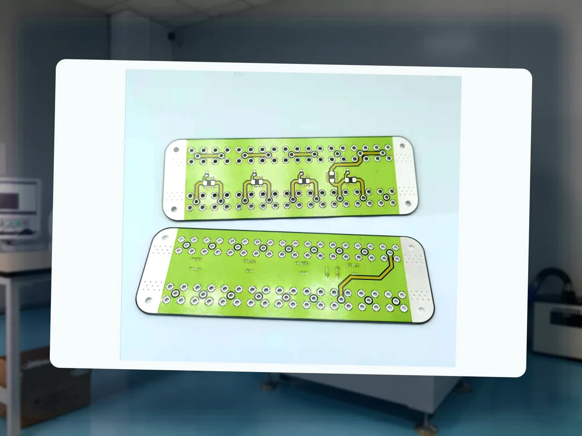
Thick-film failures are best traced backward through the process chain. Electrical drift, opens, leakage, pad lift and cracks each leave location and timing clues that connect design, printing, firing, trimming, assembly and environment.
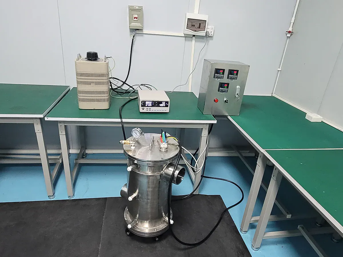
An inspection plan for custom thick-film circuits should follow critical characteristics through incoming ceramic, printed layers, firing, trimming, assembly and final test. The goal is evidence that supports function, not inspection volume for its own sake.
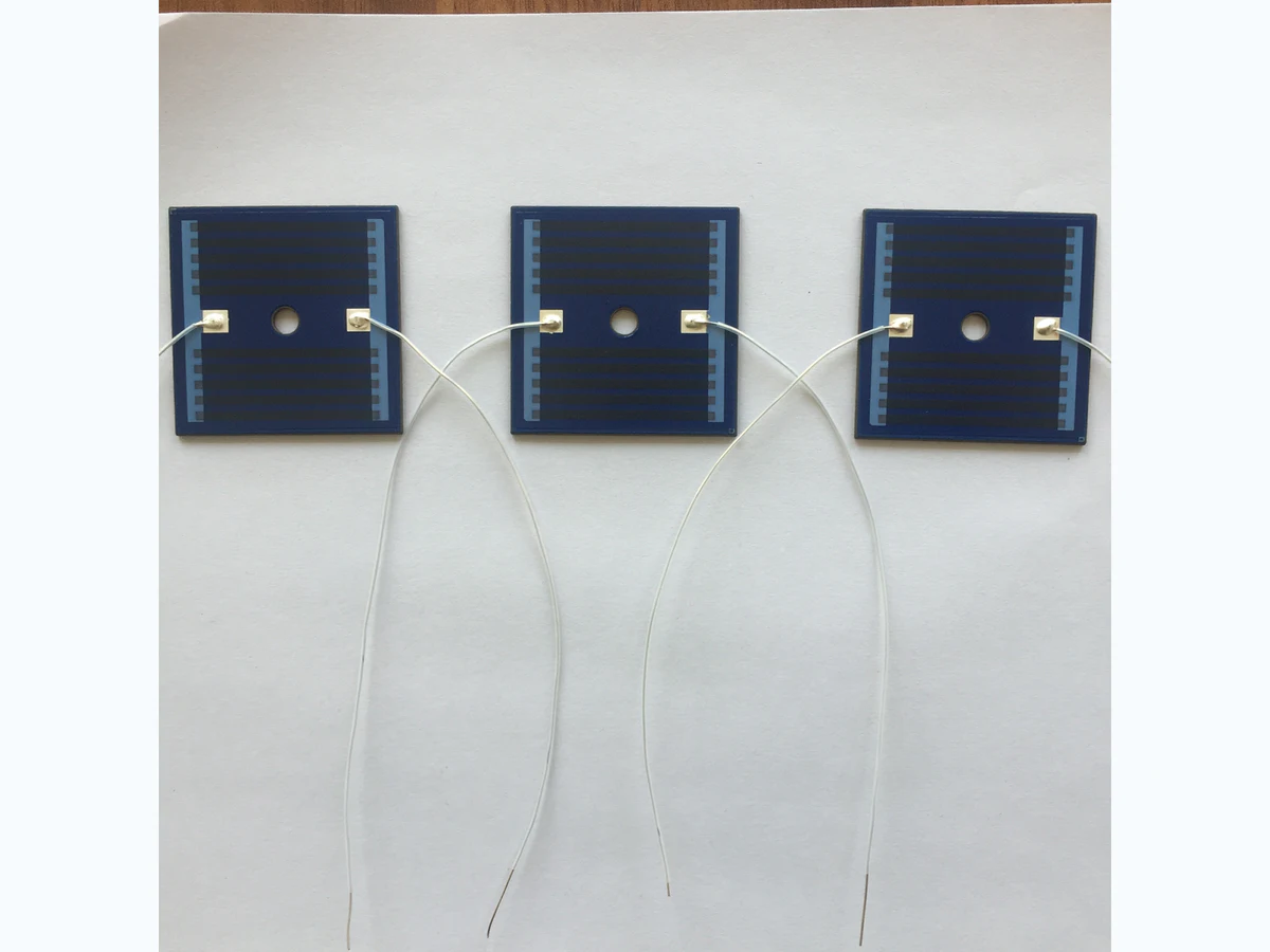
A system-level guide to heater resistance, power distribution, dielectric construction, insulation coordination, thermal mapping, controls, and abnormal-condition testing.