
On this page
- What does a finite reading across the pads tell you?
- Identify the element and its two pad nodes
- Trace the alternate paths and isolate the element
- Know where the circuit evidence runs out
- Check an OL indication and use the element reference
- Document the connections behind the diagnosis
- Questions for the design review
- Prepare an engineering RFQ
- Related engineering resources
Prepared by Chipsimple Engineering Team, Engineering and technical content review
Published online November 19, 2026 · Reviewed November 19, 2026
What does a finite reading across the pads tell you?
An ohmmeter reports the effective resistance between its two probe contacts. When the probes touch the pads of a heater element that remains connected to an assembly, the meter can see a route through the element and any alternative routes that connect the same two nodes. If the element is open and an alternative route still conducts, the display can settle on a finite resistance.
Identify the physical element and mark its two pad nodes on the schematic. For a de-energized, safely discharged assembly, verify meter operation, lead integrity and contact at those nodes. A valid finite reading establishes a conducting path between them under those test conditions. If another path is present, the identity of the conductor remains unresolved. An unverified probe contact leaves even the connection to the intended nodes uncertain.
Identify the element and its two pad nodes
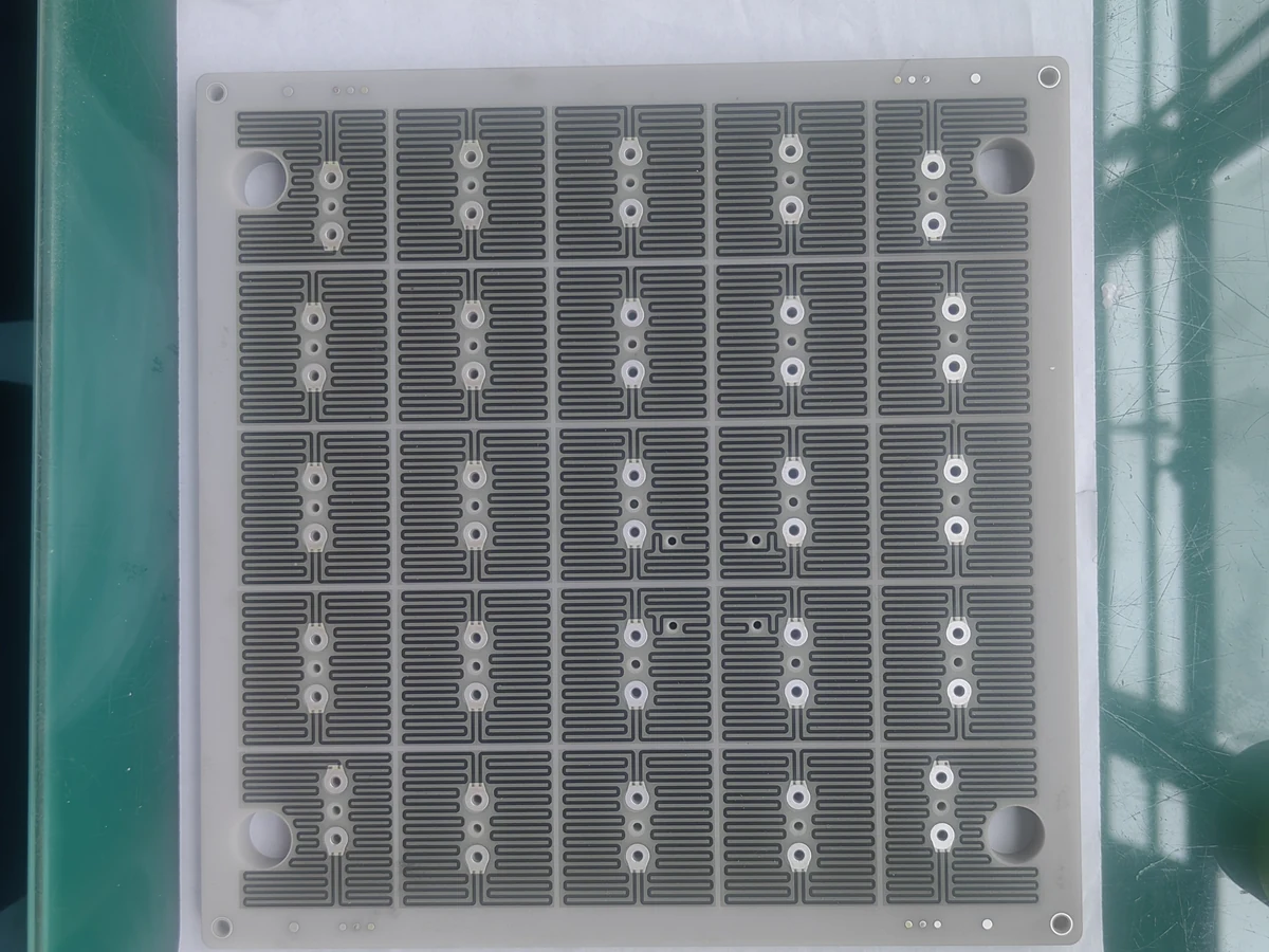
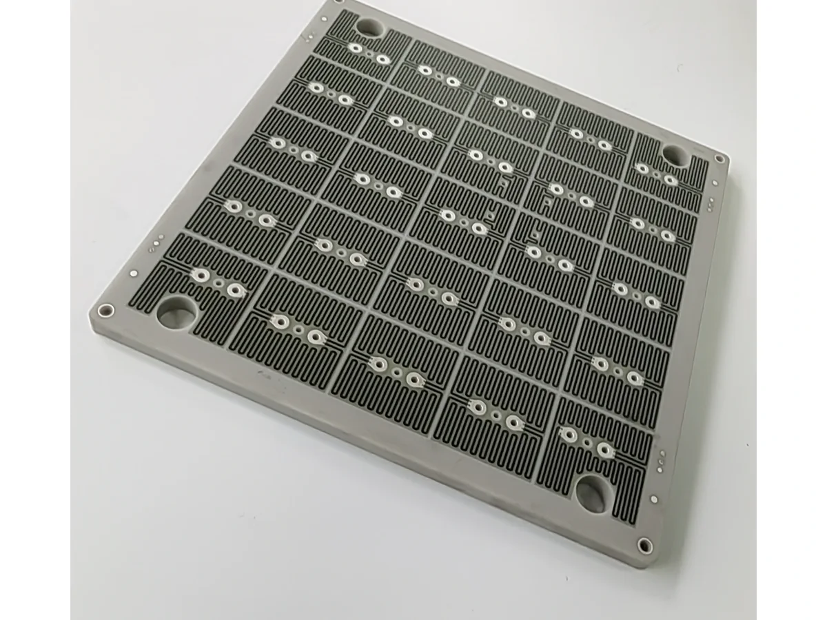
The BH390A0 drawing gives a resistance reference for each element. Use the face-on patterned photograph to orient the rows relative to the panel edges, then use the oblique patterned view to locate the paired contact areas. Find the chosen element on the applicable drawing and confirm which electrical nodes each pad connects to. The photos alone establish no connection scheme.
Match those pads to two electrical nodes on the assembly schematic. A node can include connections beyond the visible pad, so the routes that matter can extend beyond the selected element or panel. The individual resistance references apply at the element level. The assembly schematic and actual connection state provide the evidence for how the two test nodes are joined in the assembly under test.
Trace the alternate paths and isolate the element
Before connecting the ohmmeter, de-energize the assembly and discharge stored energy using the equipment-approved procedure. On the assembly schematic, trace every complete route from the first pad node to the second. Include routes that pass through other connected parts of the assembly. A chain of components can form an alternative branch if the ends of that chain connect to the same two nodes as the selected element.
For an ohmic element and one alternative ohmic path across the very same two nodes, let Re and Ra be their finite resistances under the ohmmeter test conditions. Then Rm = Re × Ra/(Re + Ra) for the two parallel paths, excluding fixture effects. If the element opens, only the alternative path carries the meter current. Rm then equals Ra if that path and its resistance remain unchanged under the test conditions. The connected reading can therefore fall near the element reference despite an open element.
Use the schematic and the equipment-approved isolation procedure to interrupt the alternative routes while keeping the element pads accessible. Verify meter operation, lead integrity and contact at the two intended pads, and confirm that only the selected element joins the probe nodes. Record the reading and the isolation state together. If the connections or contacts are uncertain, retain the display as an unresolved observation.
| Observation | What it supports | How to record or proceed |
|---|---|---|
| Finite reading with verified meter, leads and contacts at both intended pads, and an additional possible path | A conducting route exists between those probe nodes under the test conditions | Record the connected network reading. If the meter, leads or contacts are unverified, record only the observed display. |
| Finite isolated reading with verified meter operation and contact at both intended pads, and with any fixture return path excluded | A finite reading through the isolated element. The displayed value may include series lead and contact resistance. | Record the isolated reading. Compare it only if the approved element reference and its stated temperature are available, the element temperature matches, and any lead or contact resistance that could affect the comparison has been accounted for. Otherwise, leave the comparison unresolved. |
| OL before the meter, probes, and pad contacts are verified | Interpret this display using the actual meter manual, mode and selected range. | Verify meter operation, lead integrity, and contact at both intended pads before diagnosing the element |
| Persistent OL with isolation, instrument operation, and contact verified | Interpret this display using the actual meter manual, mode and selected range. | Record the indication, range, and verification checks. If the manual defines OL as over-range and the selected range is appropriate, report that no finite resistance within that range was measured. An open remains a possible explanation. |
Know where the circuit evidence runs out
Before comparing the reading with the listed element reference, use the assembly schematic and the documented connection state to verify that the meter measures the element in isolation. A reading close to the reference still requires that verification.
When the equipment procedure provides no way to isolate the selected element, label a finite result as equivalent network resistance and leave the individual element unresolved. The same limit applies when the schematic or the documented connection state is incomplete and you cannot establish which routes remain. Keep the identity of the selected element and the exact probe nodes with the result so the scope of the observation is clear.
Check an OL indication and use the element reference
Fluke’s meter guide gives an example in resistance mode: an open circuit produces OL because the resistance is above the meter’s measurement range. Check the manual for the actual instrument, select an appropriate range, verify meter operation and leads, and confirm contact at both intended pads. After branch isolation, a persistent over-range display establishes that the meter found no finite resistance within that range. An open element is one possible explanation.
Compare a finite isolated reading only with the approved resistance reference for that specific element at the temperature stated for the reference. Account for any lead or contact resistance that could affect the comparison. Document the temperature associated with the reading. If the reference or its stated temperature is unavailable, the test temperature does not match, or relevant lead or contact resistance cannot be accounted for, report the isolated reading and leave the comparison unresolved.
Document the connections behind the diagnosis
Keep the element identifier, panel orientation, and two pad nodes together in the test record. Include the assembly schematic that applies to the unit under test and indicate the paths it shows between the nodes. Record the actual connection state for each measurement, including the connection changes used for isolation. That detail lets another reader determine whether the display represented the individual element or the connected network.
Record the meter indication, the instrument and probe contact checks, and whether any attached fixture provides another conducting path between the probes. A confirmed isolated path permits an element-level interpretation. If an alternative path remains, including one through an attached fixture, record a finite reading as equivalent network resistance. For any reference comparison, record the temperature and reference used and how you accounted for lead or contact resistance that could affect the comparison. If you cannot account for that resistance, leave the comparison unresolved. When the isolation or contact evidence is incomplete, identify the missing evidence and leave the element diagnosis open.
Questions for the design review
Can a reading close to the element reference rule out an open?
A connected branch can produce a reading close to the element reference even if the element is open. Use the isolated-reading row of the table for the comparison.
Which BH390A0 view helps locate the contact areas?
Use the face-on patterned view to orient the repeated units by the rows and panel edges, and the oblique patterned view to locate the paired contact areas. The applicable element drawing and assembly schematic identify the two electrical nodes.
Does this resistance check assess heater insulation?
This check addresses continuity and resistance along the heater element’s intended path between its two pads. Insulation assessment requires its own test and acceptance criteria.
Prepare an engineering RFQ
- Element identifier, panel orientation, and the two intended probe pads
- Assembly schematic and identification of all paths between the pad nodes
- Equipment procedure for de-energizing, discharging stored energy, and isolating the element
- Actual connection state and any isolation changes for each reading
- Meter indication and range, checks on meter, leads and contacts, and assessment or correction of consequential lead and contact resistance
- Approved resistance reference, its stated temperature, and the element temperature for comparison