
On this page
- Which resistance must stay within the drift budget?
- Read the heading and the footnotes before the percentage
- Work the two-term allowance at 100 ohms
- Check whether the two stress conditions are comparable
- Apply a project requirement to the proposed custom element
- Record what the comparison supports
- Questions for the design review
- Prepare an engineering RFQ
- Related engineering resources
Prepared by Chipsimple Engineering Team, Engineering and technical content review
Published online November 19, 2026 · Reviewed November 19, 2026
Which resistance must stay within the drift budget?
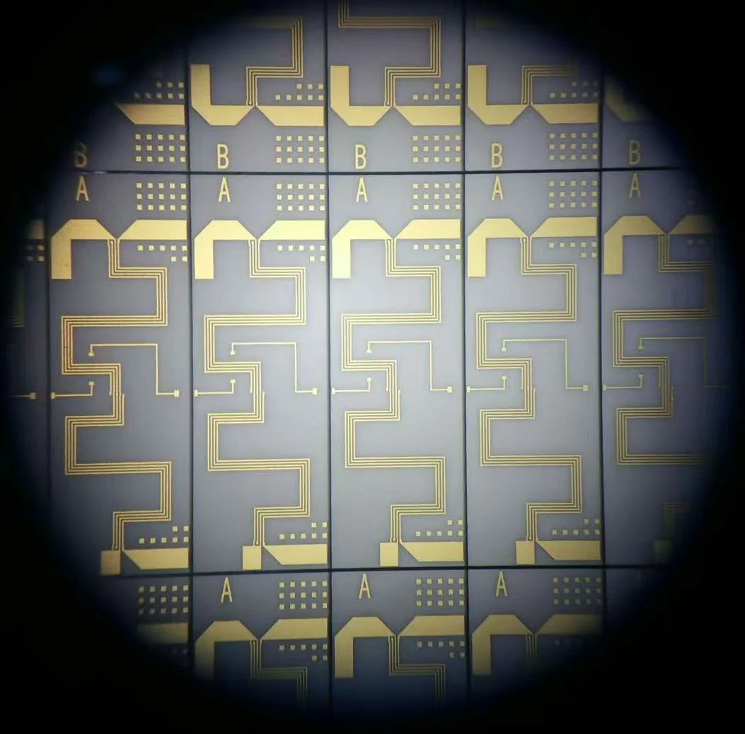
On the panel photograph, the folded patterns repeat between visible row boundaries. Use that view to locate the drawing region you want the supplier to review. Mark the exact element and its two measurement terminals on the applicable circuit drawing. A photograph identifies a feature to discuss. The drawing and its specification establish whether it is the resistor of interest and what initial resistance applies.
Suppose a buyer has defined a maximum allowed change after one thousand hours under a stated endurance procedure. The question for each vendor is how much change its specification permits at the chosen resistance. This is a change from an initial resistance. A production tolerance on that initial value answers a different question, so record the initial tolerance and the endurance requirement in separate fields.
Read the heading and the footnotes before the percentage
Vishay lists different rows for general operation and power operation in its TNPW e3 thin-film series. In the specified thousand-hour endurance procedure at 70 °C, the general-operation row allows a change of either sign up to 0.05 percent of the reference resistance plus 0.01 ohm. The power-operation row allows 0.1 percent plus 0.01 ohm. Identify the applicable mode before quoting a number.
For the D/CRCW-P e3 thick-film series, the cited table covers resistance values from 100 ohms to 10 megohms. Its thousand-hour row at 70 °C allows a change of either sign up to one percent of the reference resistance plus 0.05 ohm. The same table includes a longer endurance duration with a different requirement. Copy the duration, range and series designation along with the formula.
Work the two-term allowance at 100 ohms
Take a hypothetical starting resistance of exactly 100 ohms in each applicable row. For the thin-film general-operation example, multiplying 100 ohms by 0.0005 gives 0.05 ohm. Adding the fixed 0.01 ohm gives a permissible change of 0.06 ohm in either direction. Relative to the assumed starting resistance, that is 0.06 percent. In power operation the arithmetic would yield 0.11 ohm under its own row.
For the thick-film example, one percent of 100 ohms is 1 ohm. Adding the fixed term gives 1.05 ohms in either direction, or 1.05 percent at this starting value. These figures describe what the respective requirements permit under their specified procedures. They do not give a measured change, the direction an individual unit will drift, or a general property of the two film technologies.
| Specification and mode | Allowed change in either direction | Relative to 100 ohms |
|---|---|---|
| Vishay TNPW e3, general operation | 0.05 Ω + 0.01 Ω = 0.06 Ω | 0.06% |
| Vishay TNPW e3, power operation | 0.10 Ω + 0.01 Ω = 0.11 Ω | 0.11% |
| Vishay D/CRCW-P e3, cited resistance range | 1.00 Ω + 0.05 Ω = 1.05 Ω | 1.05% |
Check whether the two stress conditions are comparable
Both cited procedures use one and a half hours on followed by half an hour off. Determine the applied test voltage from the applicable power rating at 70 °C, P70, and the resistance under the procedure. Limit that applied voltage to the specified part voltage ceiling. TNPW e3 denotes that ceiling Umax. The ceiling and the power-derived voltage need not be the same, so equal time and temperature alone do not establish equal loads.
Include the package, operating mode and applicable test load in the comparison alongside the allowed change. If one specification is silent about the intended load or gives a different stress condition, retain its result with that qualification. Ask for evidence at the required condition before deciding whether that candidate meets the project limit.
Apply a project requirement to the proposed custom element
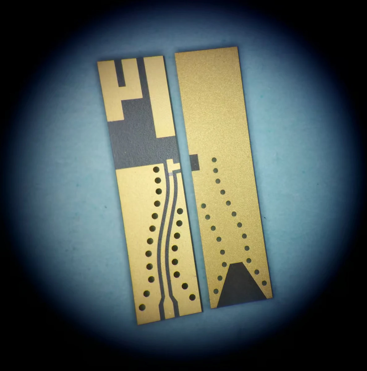
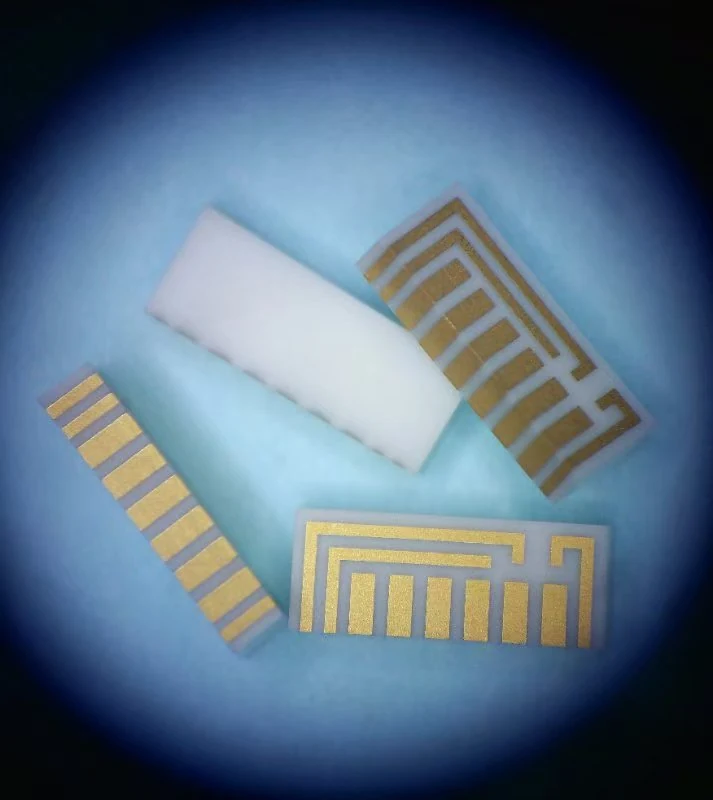
For a patterned ceramic circuit, attach a marked drawing showing where the supplier should measure resistance before and after the endurance procedure. Specify the readout conditions for both readings as defined by the applicable procedure, including the measurement temperature and the timing of the post-stress reading, with any required recovery period. The exposure temperature and on/off cycle describe the stress. The two additional photographs show visible patterns and boundaries on different samples, including repeated strip-shaped areas in one view. Use the corresponding drawing for each sample to confirm which features are terminals. Neither their appearance nor the chip examples provide an endurance rating for a resistor fabricated in one of those circuits.
Ask the supplier for the written change limit, its reference resistance, the stress duration and temperature, the load cycle, the procedure-defined readout conditions, and identification of the construction and element the limit covers. If the supplier supplies actual readings, keep those readings with their sample identifiers. A result for one tested unit and a guaranteed requirement for an entire series support different purchasing decisions.
Record what the comparison supports
If the applicable requirement is given as a fractional coefficient times the reference resistance plus a fixed number of ohms, divide the full expression by the reference resistance to obtain a relative change. The contribution from the fixed-ohm term then depends on the resistance. Recalculate it whenever the element changes value, even if the percentage shown in the table stays the same.
A comparison sheet can hold the starting resistance, the supplier procedure, the calculated allowance and the project limit together in one row per candidate. Mark whether each source is a series requirement, an individual observation or an outstanding request for the actual custom element. A thousand-hour requirement alone gives no basis to project a resistance change at a different field service duration. For the broader choice of fabrication route, the ChipSimple resistor-network selection guide is linked in the sources.
Questions for the design review
Can a sample photograph identify the applicable endurance row?
Use a marked drawing to identify the resistor and both terminals. The applicable row depends on the actual part specification, resistance and stress conditions. The supplied photographs of different circuit samples document their appearance.
Why can two values in one series have different relative allowances?
The fixed allowance is expressed in ohms. Dividing it by the reference resistance gives a larger fractional contribution at a lower resistance. Use each resistance only within the range covered by the selected table.
What if the custom network supplier quotes only an initial tolerance?
Request a separate endurance change limit for the identified element and intended stress procedure. An initial tolerance can describe the permitted starting value. It supplies no numerical bound on change during the endurance test.
Prepare an engineering RFQ
- Drawing identifier, marked element and two resistance-measurement terminals
- Reference resistance, allowable change after the specified endurance test, and procedure-defined readout conditions for the before-and-after measurements, including measurement temperature, post-stress readout timing and any required recovery period
- Duration, temperature, load, on/off cycle and relevant voltage limit
- Supplier specification, part or custom construction, package and operating mode
- Separate identification for any actual sample readings