
On this page
- Which hot face does the assembly expose?
- Set the temperatures and air boundary for the comparison
- Calculate the face-up minus face-down convection loss
- Carry the face loss into the standby heat balance
- Check the installed boundary and temperature locations
- Document the geometry and the standby allowance
- Questions for the design review
- Prepare an engineering RFQ
- Related engineering resources
Prepared by Chipsimple Engineering Team, Engineering and technical content review
Published online November 19, 2026 · Reviewed November 19, 2026
Which hot face does the assembly expose?
Identify the hot face exposed to air at steady standby and check whether it faces up or down in the installed assembly. In open, still air, a hot face pointing up can shed heat into rising buoyant plumes. Air below a downward-facing hot surface follows a different flow pattern.
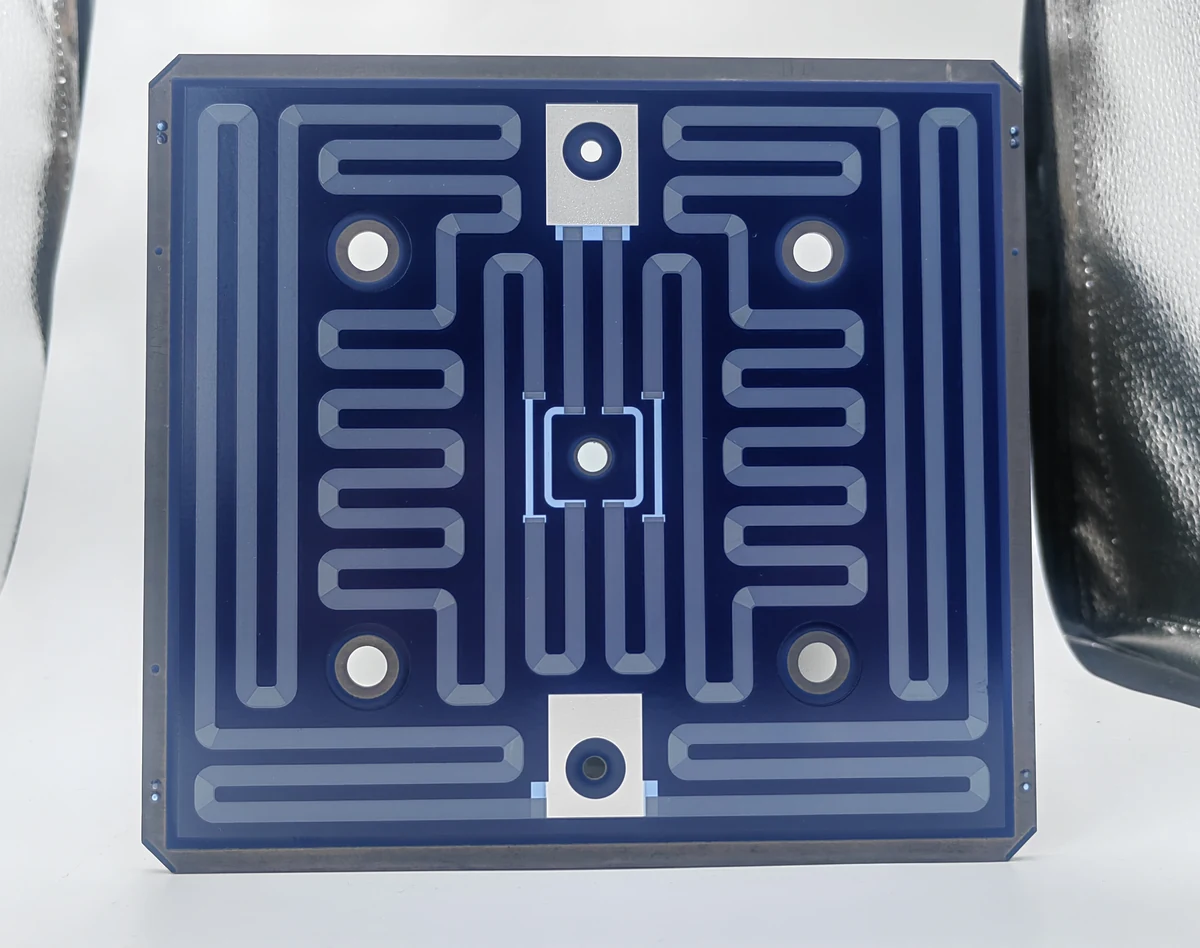
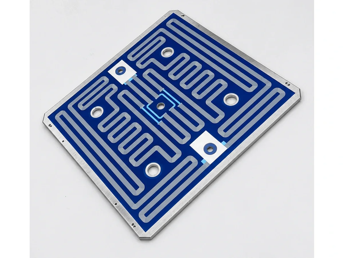
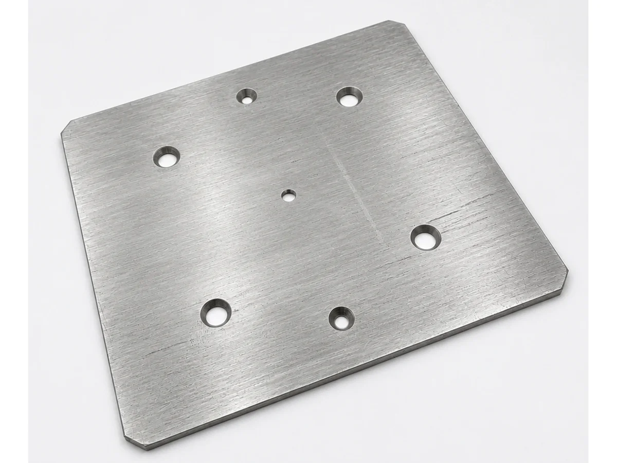
Use the BS391A0 front view to identify the patterned face by its visible track, central opening and peripheral contacts. Use the rear view to identify the back and its mounting openings. Match those landmarks to an installed section drawing and mark gravity, the surface exposed to air and the surfaces in contact with the support. The photographs identify the faces and visible geometry. The drawing establishes which face points up or down and how much of it is exposed.
Set the temperatures and air boundary for the comparison
At steady standby, a surface-temperature map can show whether the exposed hot face is approximately isothermal. A hot-spot reading alone cannot establish that condition. If significant variation persists, use a justified nonuniform-temperature treatment before quantifying convection. When an isothermal approximation is supported, use the representative face temperature and the undisturbed air temperature outside the boundary layer. Select the area-average coefficient for the actual geometry, orientation and air boundary. Keep those temperatures, geometry and air properties matched when isolating orientation alone.
Check the space adjoining the hot face in each assembly. An external natural-convection correlation requires open air space consistent with its assumptions. A nearby plate, housing wall or cover can change that boundary. Use the exposed area represented by the chosen correlation and record how the drawing and correlation treat openings and covered portions of the square face. A substantially perforated or masked face may not have the same air circulation as a plain plate. Obtain an applicable model before calculating its coefficient.
Calculate the face-up minus face-down convection loss
For a face represented by an unobstructed horizontal plate, ASHRAE gives the characteristic length L = A/P, where A is the area of one face and P is the plate perimeter. For a solid square of side a this gives L = a/4. Evaluate air properties at the mean of the face and ambient temperatures. Calculate Ra = g β (Ts − Ta) L³/(ν α), using gravitational acceleration g, the thermal expansion coefficient β, kinematic viscosity ν and thermal diffusivity α of air. Use m² for A, m for P and L, K for Ts and Ta, m/s² for g, K⁻¹ for β, and m²/s for ν and α. If central openings or nearby obstructions appreciably alter the flow, use a correlation or measurement that represents that geometry before assigning a number to the actual part. P is the perimeter of the plate geometry represented by the relation. Adding a hole perimeter to P cannot demonstrate that the relation works for a perforated plate.
In ASHRAE Table 9, the face-up hot-plate relation T9.7, Nu = 0.54 Ra^(1/4), applies between 22,000 and 8,000,000, exclusive. The hot-face-down relation T9.9, Nu = 0.27 Ra^(1/4), applies between 100,000 and 10,000,000,000, exclusive. For this pair, compare both orientations only inside their shared interval, above 100,000 and below 8,000,000. Convert each mean Nusselt number to h = k Nu/L using air conductivity k in W/(m·K) and L in m to obtain h in W/(m²·K). For identical plate geometry including exposed area and perimeter, identical air properties and gravity, and matched approximately uniform face temperatures Ts and undisturbed air temperatures Ta, the signed face-up minus face-down convection loss is A(Ts − Ta)(hup − hdown) in W. With the same L and Ra strictly inside that shared interval, the two formula coefficients give hup = 2 hdown.
When reversing the heater changes the exposed area or geometry, keep the surface and ambient temperatures matched if comparing geometry and orientation alone. Calculate hA(Ts − Ta) for each configuration with its own applicable area-average coefficient and area. Subtract face-down from face-up. If either temperature differs, identify the temperature difference for each case: the calculated change now also contains that effect. If the published correlations do not represent the opening or air space, use another model validated for that geometry or representative steady measurements that isolate face convection at the defined endpoints. With none of these available for both orientations, leave the numerical difference unresolved.
| Installed condition | Calculation decision | Design-review evidence |
|---|---|---|
| Hot face points up into open air | Use the upward-facing hot-surface correlation within its stated range. | Exposed area, air clearance, characteristic length and Rayleigh-number check |
| Hot face points down into open air | Use the downward-facing hot-surface correlation within its stated range. | Geometry below the face, characteristic length and Rayleigh-number check |
| Only orientation changes: same plate area and perimeter, geometry, air properties and face and free-air temperatures | Within the shared validity range of T9.7 and T9.9, the predicted face-up convection loss is twice the face-down loss. Subtract the face-down loss from the face-up loss to find the signed difference. | Matching L and Rayleigh number, valid area-averaged h for each orientation and evidence that the plate geometry is represented |
| A wall or cover restricts the air space | Check whether the external correlation applies before assigning a face-loss allowance. | Section drawing with clearances and surrounding boundaries |
| Reversing the heater changes its support contact | Recalculate the attachment and housing path for each configuration. | Contact stack and temperature endpoints for each installation |
Carry the face loss into the standby heat balance
Treat the exposed-face result as a convection subtotal. Mark the heater surface and the undisturbed air outside its convective boundary layer on the installed section. Use their temperatures as the endpoints for the face-convection calculation.
Trace heat from the film through the substrate and identify any path through the attachment and housing to the surroundings. Several steps can occur in series along one path, while heat can leave through multiple paths in parallel. When conduction through the attachment feeds convection from the housing, count the heat leaving that branch once. Use the temperature endpoints appropriate to each path, and check whether reversal changes the support contact, the path resistance or its temperature endpoints.
For an installed standby budget, draw the boundary around the assembly and list the distinct heat paths that cross it. Include net radiation to the surroundings when material. Reversal can expose a different surface emissivity or a different radiative environment even at the same surface temperature. Quantify the applicable exchange, or justify its omission at the required accuracy.
Check the installed boundary and temperature locations
Check the exposed area and adjoining free space against the selected correlation. Verify a surface temperature representative of an approximately isothermal face and the undisturbed air temperature at steady standby. When the face temperature is significantly nonuniform, use a supported treatment of that distribution. A measured temperature inside the substrate needs an established relation to the exposed face before it can be used for this purpose.
For a steady full-budget check, define the thermal control volume and measure the time-average of instantaneous voltage times current at the correct electrical boundary. Use instrumentation with sufficient bandwidth to capture the relevant components of both waveforms. Include complete drive cycles for periodic input. Identify lead, connector and controller dissipation outside the control volume and exclude it from any upstream power reading used for comparison. Account separately for other power inputs or energy transfers crossing the chosen boundary. Match actual mounting, ambient and thermal conditions to the calculation.
Document the geometry and the standby allowance
Include a section drawing that identifies the patterned face and back, shows gravity and dimensions the air space and exposed area. Mark openings and surfaces covered by the attachment or housing. State the standby temperature requirement, its location and the ambient condition. If both mounting orientations are under consideration, provide the geometry and contact stack for each.
Record the selected correlation, characteristic length, applicable Rayleigh-number range, calculated Rayleigh number, area-average coefficient and face loss for each orientation. Report the signed convection difference. For a complete standby budget, record heat paths through the assembly and net radiation for each applicable exposed surface, including its emissivity and radiative surroundings, or document why it is negligible. If steady average electrical input is measured, identify its sampling boundary and any adjustment for external losses.
Questions for the design review
Does the patterned face always count as the exposed hot face?
The assembly determines which face borders air. Use the track, opening and contacts to identify the patterned face, then use the installed section drawing to determine which face is exposed and whether it points up or down.
Can I use the square edge length in both calculations?
For these two ASHRAE relations use the area of one face and the perimeter of the plain plate represented by the correlation. For a solid square L is a quarter of its side. Adding the edge length of an opening to the perimeter of a reference square does not qualify a perforated heater. Obtain an applicable correlation or experimental evidence when openings or nearby surfaces materially alter the air flow.
Can the exposed-face convection calculation set the total standby power?
Exposed-face convection contributes one term. Complete the selected control-volume balance with support and housing paths, net radiation at applicable boundaries and any other energy transfers. Quantify radiation for the relevant surface and surroundings or show that its omission is justified. A steady electrical comparison must use average real power at the same boundary.
Prepare an engineering RFQ
- Thick film heater drawing with face identification, square perimeter dimensions and opening locations.
- Installed section showing gravity, the face exposed to air and the exposed area for each configuration.
- Clearances to nearby walls and covers, with the surrounding air space shown.
- For the convection estimate in each orientation: representative approximately uniform face temperature and undisturbed ambient air temperature. Identify the location of the separate standby setpoint.
- Attachment contact area, clamping arrangement and housing boundaries.
- Thermal control volume, electrical voltage and current measurement boundaries, averaging interval, evidence that the instrumentation bandwidth covers the relevant voltage and current waveform components, and any lead, connector or controller dissipation outside that volume.
- For a complete standby budget: emissivity, radiative surroundings and all remaining heat-transfer paths for each configuration.
Related engineering resources
Measurement definitions and references
- BS391A0 Square Stainless Steel Heater — public drawing reference
- Lienhard V & IV, A Heat Transfer Textbook, 6/e (2024), §8.4, horizontal plates, Fig. 8.8 and eqs. 8.37
- MIT Introduction to Heat Transfer — convection and thermal radiation
- Yokogawa — measuring electrical power
- ASHRAE Handbook—Fundamentals, Ch. 4, Table 9: Horizontal plates