
On this page
- Which pads must be electrically isolated in the finished circuit?
- What the nickel-gold designation tells you
- Trace the conductive path from the cathode contact to each target
- Resolve gaps in the proposed connectivity
- Compare the supplier’s delivered record with the approved finished-state netlist
- What to include in the finish request
- Questions for the design review
- Prepare an engineering RFQ
- Related engineering resources
Prepared by Chipsimple Engineering Team, Engineering and technical content review
Published online November 19, 2026 · Reviewed November 19, 2026
Which pads must be electrically isolated in the finished circuit?
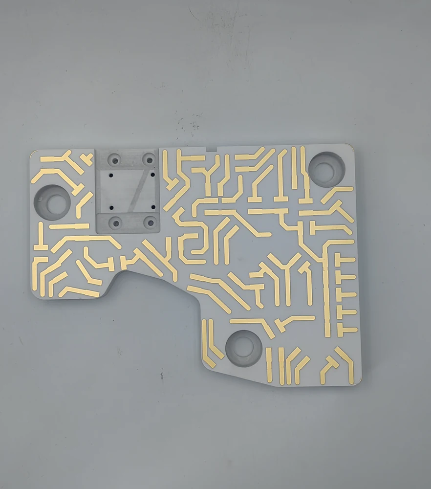
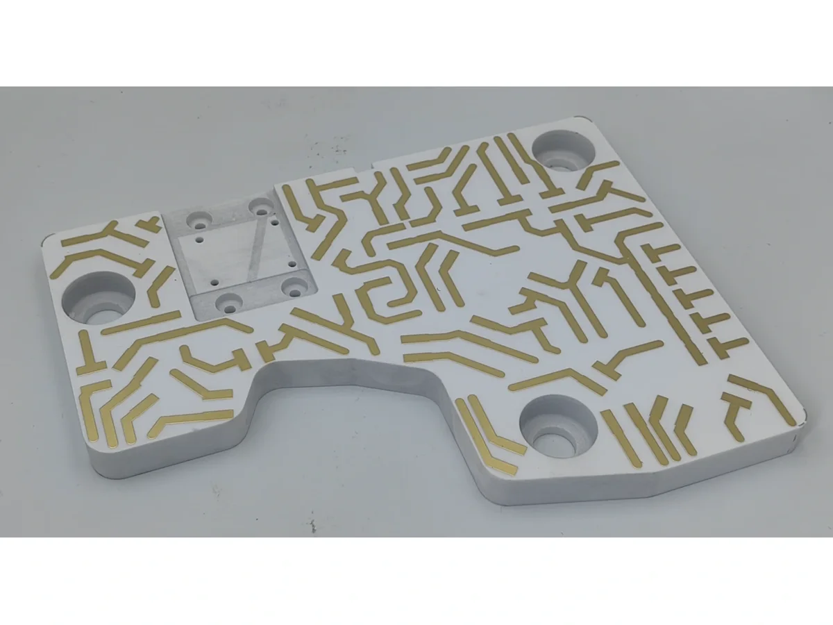
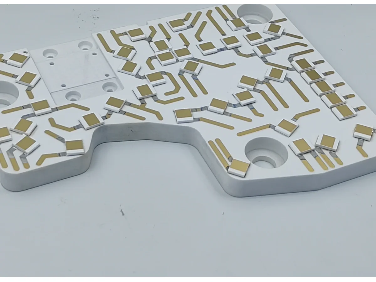
A pad can receive electroplating current through a temporary conductor and be electrically isolated in the finished circuit if the temporary path is disconnected and the required finished topology is preserved. Whether a temporary conductor is needed depends on the supplier’s process. In the BH209A0-1 views, the outline cutout, mounting openings and separate surface patterns help orient the drawing. Use those landmarks to locate features and the project circuit documentation to identify the required isolation.
The product example identifies selected nickel-gold surfaces. A finish description alone does not show how those surfaces were deposited. If the project proposal documents a temporary link for an electrolytic layer, determine when it is available for plating and how the supplier intends to disconnect it. For the pictured finish, see “BH209A0-1 Metallized Alumina Substrate”.
What the nickel-gold designation tells you
The finished isolation requirement concerns electrical behavior at delivery. Current access concerns a particular intermediate stage. A location that appears disconnected on the finished drawing can have a process connection at the earlier stage. The supplier’s proposal describes the intended connectivity at each process step and at delivery. For the actual specimen, use its delivered configuration and its electrical test results to verify the specified isolation.
Nickel-gold identifies the specified finish. The deposition method depends on the conductor and film system. Ask the supplier which layers use electrolytic or electroless deposition, and record any unspecified method as an open item. For drawing a selective coverage boundary, see “How Ceramic Metallization Forms a Pattern and How to Specify a Selective Finish”.
Trace the conductive path from the cathode contact to each target
For each proposed electrolytic step, record the finish layer, identify the supplier’s proposed cathode contact, and list every target by its approved drawing feature ID and finished net. Trace a continuous conductive path from that contact to each target at that step. Identify any temporary links and retained connections by feature ID. List targets absent from the diagram as unresolved.
One published process illustrates the principle with a removable conductive bus layer that supplies current to exposed traces during electrodeposition. Removing the layer afterward allows features that shared a current path during plating to be electrically separate in the finished circuit. Treat this as one possible arrangement and evaluate the supplier’s actual proposal against the target list and required finished connectivity.
| Condition | Evidence to examine | Decision |
|---|---|---|
| Nickel-gold specified with deposition method open | Supplier’s deposition method for each finish layer | Determine which steps require a plating current path. |
| Electroplating step includes a target required to be isolated in the finished circuit | During-plating diagram showing the cathode contact and keyed to the drawing | Trace the conductive path from the cathode contact to the target or leave current access unresolved. |
| Temporary connection present during plating | During-plating diagram and planned disconnection or removal, keyed to drawing features and the approved final netlist. | Identify the connections to retain and the temporary links to disconnect or remove. A disconnected remnant may remain if the required electrical separation is met and the drawing permits it. |
| Finished isolation and any required physical removal | Delivered-configuration record and specimen-specific electrical results; separate inspection evidence when physical removal is specified. | Record the result for the tested pair and specimen under its agreed criterion. Record any sampling-based lot decision separately. |
Resolve gaps in the proposed connectivity
When a proposed process diagram leaves a route unresolved, name the specific layer, target and missing connection. A common bus reaching one pad does not by itself demonstrate a path to the next pad. Ask for the step-specific topology and confirm which connections remain when the step is carried out.
For a proposed link that bridges two required finished nets, request the feature identifier, the intended point of disconnection and the drawing state in which they are separated. Keep the planned removal decision unresolved if the drawing leaves a stub or segment electrically ambiguous. Actual specimen acceptance and physical-removal evidence belong to the subsequent verification step.
Compare the supplier’s delivered record with the approved finished-state netlist
Compare the as-delivered configuration record with the approved final netlist at the applicable revision. In the agreed electrical test method, specify the probe points for each named net pair, the state of other nets and any connected circuitry during the test, and the applicable stimulus and time at which to take the reading. For every tested combination of specimen ID and named net pair, state the actual result, method, conditions, acceptance limit and pass or fail. Document a lot disposition separately with the agreed sampling plan and lot identity.
Where the drawing requires physical removal of a feature, separately inspect that named bus or stub against its specified removal boundary and criterion. A disconnected remnant can pass an isolation test. Retain the feature-level inspection record alongside the electrical results so the two observations can be traced to the relevant part or lot.
What to include in the finish request
Provide the substrate drawing, the intended finished netlist, and a list of selected finish surfaces. Include the applicable conductor and layer system and any masking requirements. Keep the identifiers for pads, lead-out areas, and other finish targets consistent across the documents so the supplier can identify both the surfaces to finish and the electrical separations to preserve.
Ask the supplier to identify the deposition method for each finish layer. For each proposed electrolytic step, request the cathode contact, the conductive path from that contact to each target, and documentation of how temporary links are disconnected or removed in the finished circuit. Specify the delivered netlist and agree on the electrical acceptance method so the documentation and checks address the same finished isolation requirements.
Questions for the design review
Can the photograph show which pads belong to different nets?
Use the visible cutout, mounting openings and separated surface metal patterns as landmarks to match the photograph to the drawing. Use the drawing feature IDs and final netlist to identify the electrical nodes.
Does a later-isolated pad imply that the supplier used a removable bus layer?
A removable bus layer is one documented way to supply plating current temporarily. The supplier’s deposition method and during-plating diagram establish the arrangement proposed for this circuit.
What if the supplier confirms electroless deposition for a layer?
The electrolytic current-path check applies to layers deposited electrolytically. The finished drawing and agreed isolation acceptance criteria still apply.
Prepare an engineering RFQ
- Final circuit drawing and intended netlist with the features that must remain electrically separate
- Selected finish surfaces keyed to drawing identifiers, with an annotated photo if helpful for orientation
- Conductor and finish layer system, masking requirements, and proposed deposition method for each layer
- For every proposed electrolytic step, the cathode contact and conductive path to each target, with temporary links and retained connections identified by feature ID
- Supplier record of delivered configuration, approved final netlist revision, and any removal-inspection feature, boundary and criterion
- Specimen- and net-pair-specific isolation records with their agreed test conditions and limits, plus any required removal inspection. If a lot decision is requested, include traceability and the agreed sampling plan.
Related engineering resources
- How Ceramic Metallization Forms a Pattern and How to Specify a Selective Finish
- BH209A0-1 Metallized Alumina Substrate